Example 3 - Koch boxes
Result files and dimension comparisons
Example 1 - Koch island
s    log(1/s)     N(s)  log(N(s))
-    ---------  ------  ---------
1     0.000000   61746  11.0308
2    -0.693147   17488   9.76927
4    -1.38629     6395   8.76327
8    -2.07944     2323   7.75061
16   -2.77259      829   6.72022
32   -3.46574      274   5.61313
64   -4.15888      100   4.60517
128  -4.85203      112   4.7185
256  -5.54518      144   4.96981
512  -6.23832       49   3.89182
The correct fractal dimension is 1.5.
The computed slope is approximately 1.53 (1.8% error).
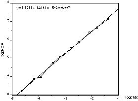
Example 2 - Koch coastline
s    log(1/s)     N(s)  log(N(s))
-    ---------  ------  ---------
4    -1.38629     1234   7.11802
6    -1.79176      798   6.68211
8    -2.07944      597   6.39192
12   -2.48491      358   5.88053
16   -2.77259      251   5.52545
24   -3.17805      159   5.0689
32   -3.46574      115   4.74493
50   -3.91202       54   3.98898
64   -4.15888       49   3.89182
100  -4.60517       25   3.21888
The correct fractal dimension is log(4)/log(3) = 1.262
The computed slope is approximately 1.22 (3.6% error).
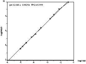
Example 3 - Koch boxes
s    log(1/s)     N(s)  log(N(s))
-    ---------  ------  ---------
4     -1.38629   21668   9.98359
8     -2.07944    8075   8.99653
12    -2.48491    3793   8.24091
16    -2.77259    2206   7.69894
32    -3.46574     620   6.42972
48    -3.8712      274   5.61313
64    -4.15888     174   5.15906
96    -4.56435      81   4.39445
128   -4.85203      49   3.89182
150   -5.01064      36   3.58352
The correct fractal dimension is log(7)/log(3) = 1.771.
The computed slope is approximately 1.80 (1.8% error).
Menus and dialogs
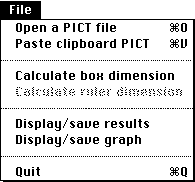
The file menu allows images to be imported into FDC either via the clipboard or
from a PICT file. In either case the image is converted into black and white if
it is colour.
After computing the box dimension the results can be displayed, the saving of
results is from the results display dialog.
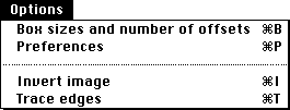
The box size dialog allows the user to set box sizes and number of random
offsets. when an image is imported into FDC these values are set to
"intelligent" defaults.
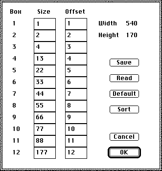
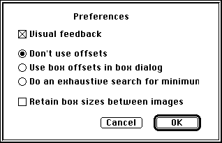
Experiment with these although most of them should be obvious. Without visual
feedback the algorithm will run faster but the indication of progress is
normally worth the speed loss.
In general only use offsets for the final analysis when the optimal box sizes
are known.
Special cases
The box dimension can also be used to measure the dimension of nonfractal
objects, namely a line and a rectangle. These were used as a test of the
algorithm.
Example 4 - Line
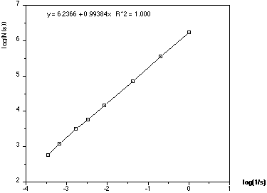
The dimension should of course be 1, measured dimension is 0.994 (0.6% error)
Example 5 - Rectangle
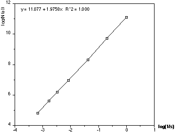
The correct dimension is 2, measured dimension is 1.976 (1.2% error)
Mesh offsets
To get an unbiased estimate using the box counting method it is necessary to
find the minimum number of boxes of a particular size that cover the object.
This can be achieved by offsetting the origin of the box mesh. The following
show the results of finding the minimum number of boxes for the Koch island
(dimension=1.5). The estimate of the fractal dimension has reduced from an error
of 1.3% to 1%. This is not an exhaustive analysis on whether or not mesh
offsets are important, but in this case the extra processing time hardly
warranted half a percent decrease in error.
s     log(1/s)    N(s)  log(N(s))   Nmin(s)  Nmax(s)  log(Nmin(s))  log(Nmax(s))
-     --------   -----  ---------   -------  -------  ------------  ------------
1     0.000000   61746  11.03080     61746    61746     11.03080     11.03080
2    -0.693147   20158   9.91136     17488    21745      9.76927      9.98714
4    -1.38629     6780   8.82173      6395     7402      8.76327      8.90951
8    -2.07944     2359   7.76599      2297     2399      7.73936      7.78281
12   -2.48491     1300   7.17012      1270     1335      7.14677      7.19669
16   -2.77259      852   6.74759       825      886      6.71538      6.78672
24   -3.17805      468   6.14847       452      475      6.11368      6.16331
32   -3.46574      296   5.69036       279      314      5.63121      5.74939
64   -4.15888      106   4.66344       102      110      4.62497      4.70048
96   -4.56435       58   4.06044        56       62      4.02535      4.12713
128  -4.85203       37   3.61092        32       40      3.46574      3.68888
256  -5.54518        3   1.09861        12       15      2.48491      2.70805
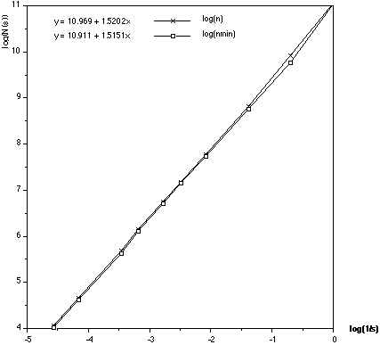
If the result where s = 1 (log(1/s) = 0) is removed a much closer estimate of D
is obtained (approximately 0.2% error).
Technical Notes
This software requires a Macintosh computer equipped with 32bit QuickDraw.
This is built into the newer colour machines from Apple and is available as an
extension for the older colour capable machines. It is required because of the
use of offscreen bitmaps used by this application. Note that a colour or grey
scale monitor is not necessary for this software although it is recommended.
Because the program reads Macintosh PICT files (or clipboard PICT items) the
format of the contents is not important as PICT files are handled by the
operating system. For example, the program will accept PICT files containing
object orientated data from CAD or drawing programs as well as the more usual
bitmaps from fractal generation packages. It will also accept the JPEG
compressed images now possible through QuickTime.
The user is required to create the appropriate black and white image. If a
colour PICT is opened then it will be converted to black and white internally
by a method chosen by the Macintosh toolbox. Because there is no control (or
intelligence) involved in this process it is recommended that the image be
converted to black and white beforehand. There are many products that can do
this and then save as PICT, for example, Adobe PhotoShop.
If the image does not fit on the screen it will be reduced by an integer
scale factor until it does. There are advantages in using large images, a wider
range of box sizes are possible and therefore the resulting estimate of D will
generally be better. The reduction factor is shown as part of the window name.
IMPORTANT: this is only a visual reduction, the entire image resolution is
retained internally for computational purposes.
The area outside the image rectangle is assumed to be empty (white) If the
object under study extends past the rectangle in reality then it should be
noted that the software effectively truncates it at the image rectangle
boundary.
Since the box size is limited to the pixel boundaries the number of offsets
is dependent on the box size. For example, for a 2x2 pixel box only 4 possible
random (unique) origins are possible while larger mesh sizes have many more
possible origins. To avoid the enormous time required to search all possible
origins a random number of origins are chosen for a particular box size.
Offsets can greatly increase computation time, use with care.
Clover-period will cancel box counting operations, the results will be valid
up to that point at which the cancel took place.
Box calculations will run in the background.
This software has been tested on machines from the Mac LC to the Quadra 950,
running system 6 and/or system 7. The application will run in the background
under MultiFinder or system 7, however it takes rather large chunks of
processing time and foreground application may be adversly affected.
Trace edges works by applying the following mask to the image, the 1 pixel
border of the image is set to white.

Image Preparation
This program will read and interpret any legal PICT file. This includes PICT
files containing bitmaps (the most likely for this application), objects,
colour images, and QuickTime compressed images. This application however only
works with black and white images, the black part is considered to be the
object. Thus images containing colour or grey information will be converted
into black and white using a technique provided by the Macintosh toolbox. Since
the user has little control over this conversion it is recommended that the
images be converted to black and white by the user before using this
application.
There are a number of ways of creating images for the Fractal Dimension
Calculator. Some examples of image creation might be scanning paper images,
video capture, ultrasound scanning, and slide scanning. The hardware and
software that controls these image capture devices will allow the image to be
stored in a number of image file formats. The most common format on the
Macintosh is PICT, the most common industry standard format is TIFF. In general
the user will require some additional software to convert the acquired image
into something suitable for the Fractal Dimension Calculator. The most likely
operations are: cropping (removing unwanted parts of the image), conversion to
black and white, and changing the resolution.
Cropping - this is the task of removing parts of the images that are not
necessary. There may be parts of the image that represent objects not part of
the object for which the fractal dimension is to be calculated.
Colour conversion - This is the operation of converting the colour or grey
scale image to black and white. Most programs will provide the ability to
specify an intensity threshold, pixels with an intensity less than this
threshold become white, the other pixels become black.
Resolution - images for this application should have a resolution of 72 dpi.
The "resolution" does not define the information content an image, this is
defined by the number of pixels horizontally and vertically. A resolution of
300dpi simply dictates the physical size of a pixel, namely 1/300 inch. Thus a
1 inch square image of 300x300 pixels at 300dpi is identical (information wise)
to the same image at 75dpi. The only difference is that the 75dpi image will be
4 inches square. Again, all image for this application should be converted to
72dpi.
There are many application which can be used to prepare images for Fractal
Dimension Calculator. The author uses and recommends Adobe PhotoShop.
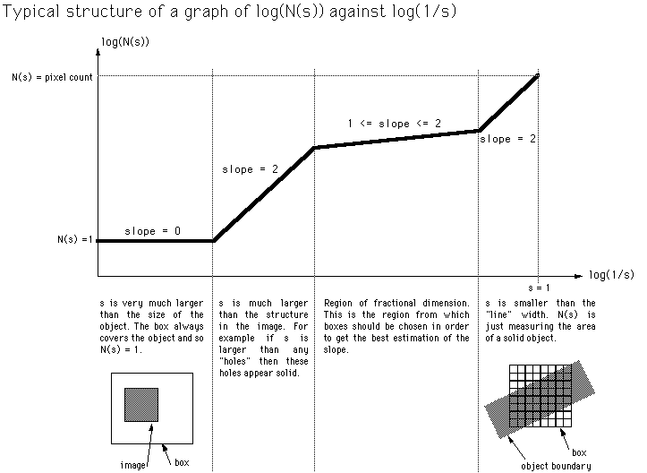
Of particular interest is the graph below illustrating the area of the graph of importance as a function of the image size, the image structure size, and the
range of box sizes used.
References
Herbert F. Jelinek, Eduardo Fernandez
Neurons and fractals: how reliable and useful are calculations
of fractal dimensions?
Journal of Neuroscience Methods, 81:9-18, 1998
Andrew Harrison
Fractals In Chemistry, Oxford Chemistry Primers
Oxford Science Publications, 1995
Larry S. Liebovitch and Tibor Toth
A fast algorithm to determine fractal dimensions by box-counting
PHYS-LETT-A, Vol 141, No 8 9, pp 386--390", Nov 1989
Xin-Jun Hou, Robert Gilmore, Gabriel B. Mindlin, Hernon G. Solari
An efficient algorithm for fast O(N/log N) box counting
PHYS-LETT-A, Vol 151, No 1 2, pp 43--46, Nov 1990
H.S. Greenside and A. Wolf and J. Swift and T. Pignataro
Impracticality of a box-counting algorithm for calculating dimensionality of
strange attractors
PHYS-REV-A, Vol 25, No 6, pp 3453--3456, Jun 1982
T.G. Smith Jr., W.B. Marks, G.D. Lang, W.H. Sheriff Jr., and E.A. Neal
A Fractal Analysis of Cell Images
Journal of Neuroscience Methods, Vol 27, pp 173-180, 1989
Heinz-Otto Peitgen
Fractals in the Classroom, Part 1
Springer-Verlag, 1991, pp 240
Heinz-Otto Peitgen, Dietmer Saupe
The Science of Fractal Images
Springer-Verlag, pp 61, 1985