Introduction
The following is an attempt to acquaint the reader with a fractal object called the Sierpinski gasket. The gasket was originally described in two dimensions but represents a family of objects in other dimensions. This family of objects will be discussed in dimensions 1, 2, 3, and an attempt will be made to visualise it in the 4th dimension. Cantor set or Dust
The nineteenth century mathematician Georg Cantor became fascinated by the infinite number of points on a line segment. The set of points described here has been attributed to Cantor because of his attempts to imagine what happens when an infinite number of line segments are removed from an initial line interval. To generate the Cantor set start with a closed interval [0,1] (includes the points 0 and 1). On the first iteration replace the interval with 3 equal length pieces and remove the middle third, or ]1/3, 2/3[ (excludes the points 1/3 and 2/3) Subsequent iterations involve removing the middle portion of the remaining line segments.. The gap removed each time is usually called a trema from the Latin tremes = termite. True Cantor dust is hard to illustrate because of its point nature. To solve this problem it is normally shown "thickened" in the vertical axis, what might be called cantor bars, the first five steps in the generation process are shown below.
"Dust" or points refer to a topological dimension of 0 just as a curve and surface denote sets of topological dimension 1 and 2 respectively. When the middle third is removed the dust is called a triadic set. The size of the piece removed can be anything giving a spread of fractional dimensions between 0 and 1. If the middle section is 1-2tau then the dimension is given by
For the Cantor set described earlier, tau = 1/3 and therefore the dimension = log 2 / log 3 = 0.6309, ie: the dimension is somewhere between a point (dimension = 0) and a line (dimension = 1) Cantor dust can readily be created using L-Systems by using the following axiom and generator.
Chaos game
An interesting method of creating the 2 dimensional gasket comes from a problem in chaos theory. Consider 3 vertices P1, P2, and P3 of a triangle as shown below. Starting at any point on the plane, point 0, choose a vertex randomly using any probability for each of the three vertices. Draw an infinitely small point on the plane half way between the current point and the vertex chosen, point 1 below, this now becomes the current point. Repeat this process indefinitely, each time drawing a point halfway between the current point and a randomly chosen vertex. What is the final distribution of points on the plane (after ignoring the first 10 say)? The following diagram shows the first 5 points drawn after randomly choosing vertices p1, p3, p3, p1, and p2. Note: the lines are not normally drawn, they are shown here to illustrate the midpoint between the current point and the vertex that was chosen.
While it is easy to understand that the points all lie within the triangle specified by the 3 vertices it is not so easy to imagine that there are "large" areas where points will never be drawn. The distribution of points form the 2D Sierpinski gasket. The points p1, p3, p3 obviously need not lie at the vertices of an equilateral triangle as above. Other positions for p1, p3, p3 just yield appropriately skewed gaskets. A simulation of the above experiment implemented as an IFS (Iterated Function System) is shown below for a range of points.
Sierpinski gasket
A geometric method of creating the gasket is to start with a triangle and cut out the middle piece as shown in the generator below. This results in three smaller triangles to which the process is continued. The nine resulting smaller triangles are cut in the same way, and so on, indefinitely.
The gasket is perfectly self similar, an attribute of many fractal images. Any triangular portion is an exact replica of the whole gasket. The dimension of the gasket is log 3 / log 2 = 1.5849, ie: it lies dimensionally between a line and a plane. Of particular interest is the area of the holes and the circumference of the solid pieces. If the area of the original triangle is 1 then the first iteration removes 1/4 of the area. The second iteration removes a further 3/16 and the third a further 9/64. The total area removed after the Nth iteration is given by
If the circumference of the original triangle is 1 then after the first iteration the circumference increases by 1/2. After the second iteration it increases by 3/4. The circumference after the Nth iteration is given by
As shown above the gasket has no area but the boundary is of infinite length. The gasket can also be generated a number of ways with a Lindenmayer system as illustrated by the axiom and generator below. On each iteration the lines (the axiom for the first iteration) are replaced by a suitably scaled version of the generator.
There are many other L-Systems that can form gasket like images, one example shown below is called the Sierpinski tiling arrowhead.
Pascals triangle Another way to create the Sierpinski gasket is via Pascals triangle. If the entry in pascals triangle is odd then it is part of the gasket otherwise it is not part of the gasket.
            1
          1   1
        1   2   1
      1   3   3   1
    1   4   6   4   1
  1   5  10  10   5   1
1   6  15  20   15  6   1
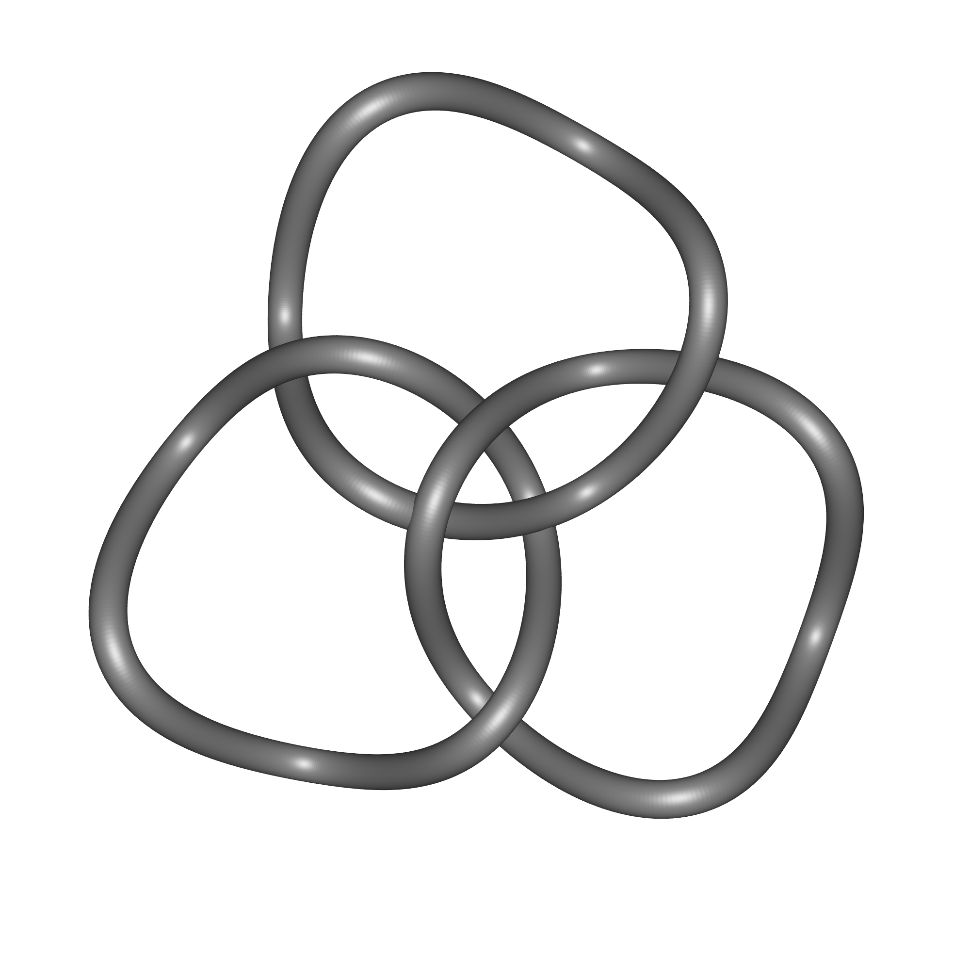
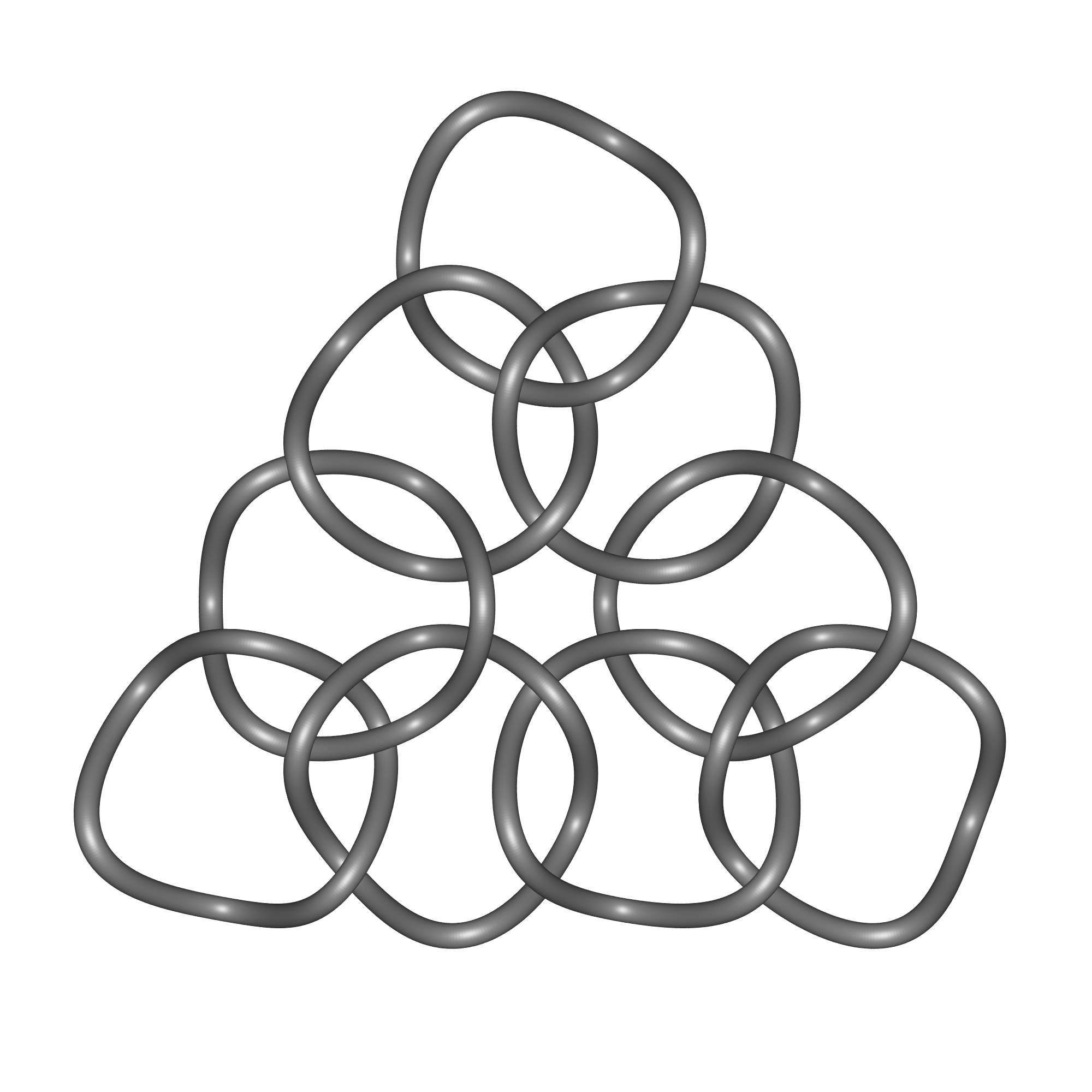
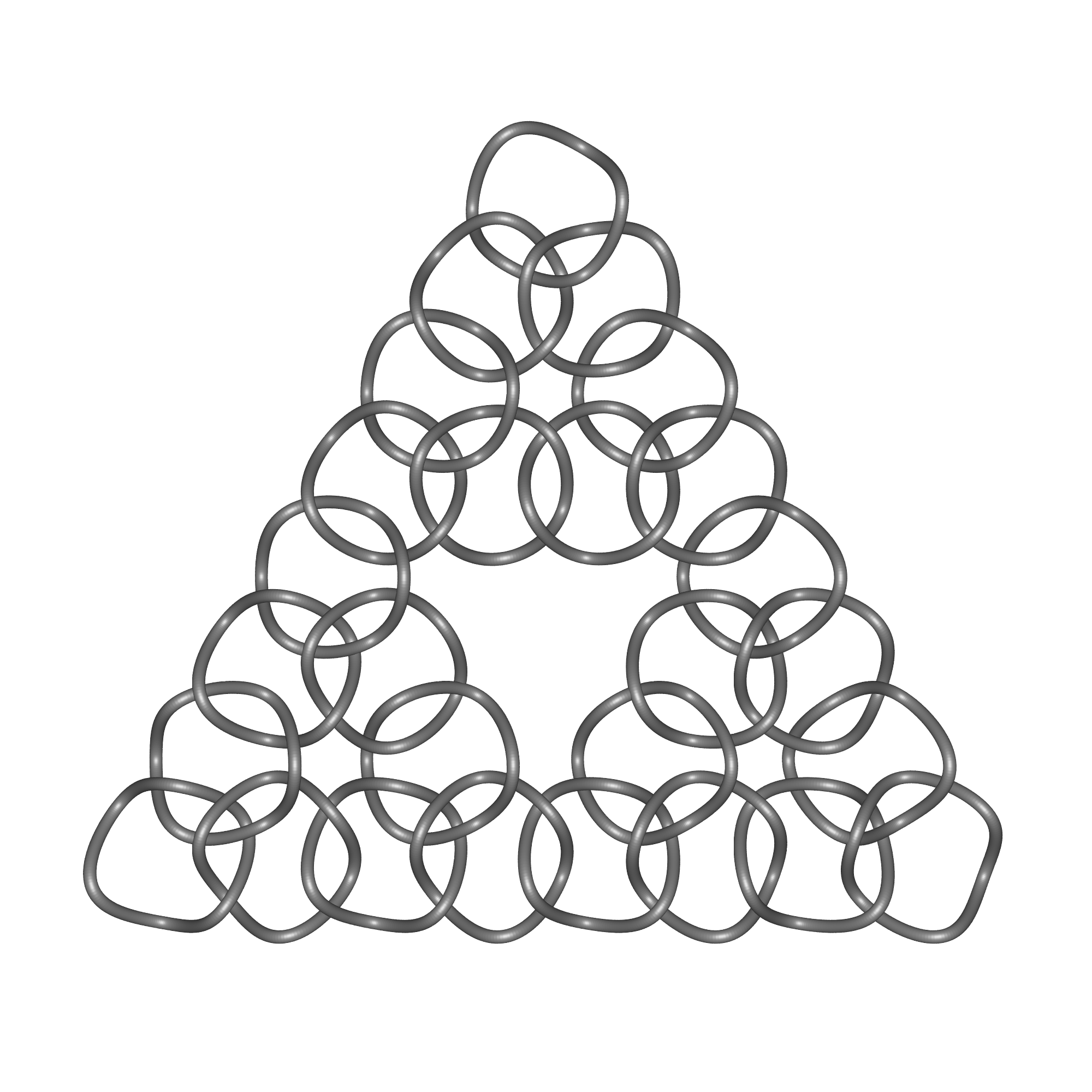
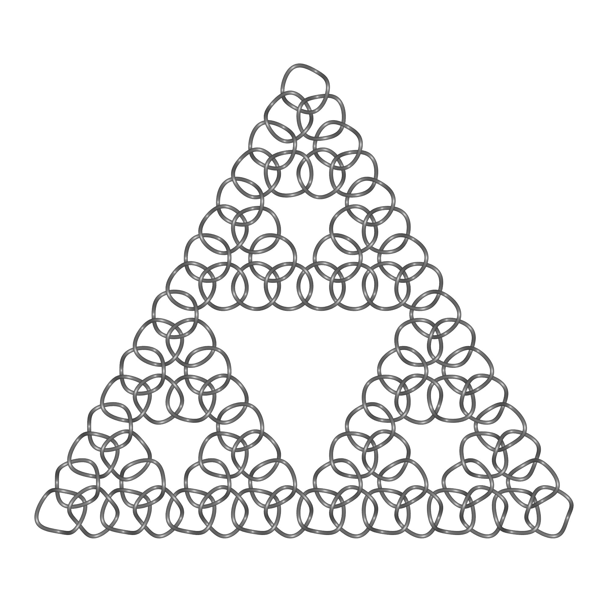
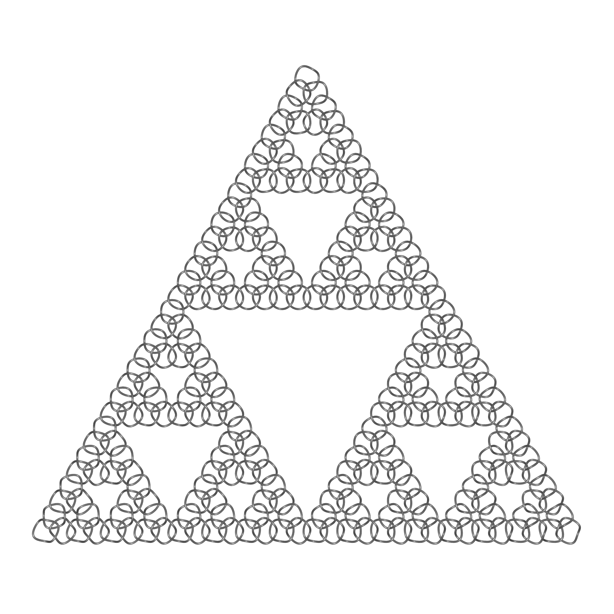
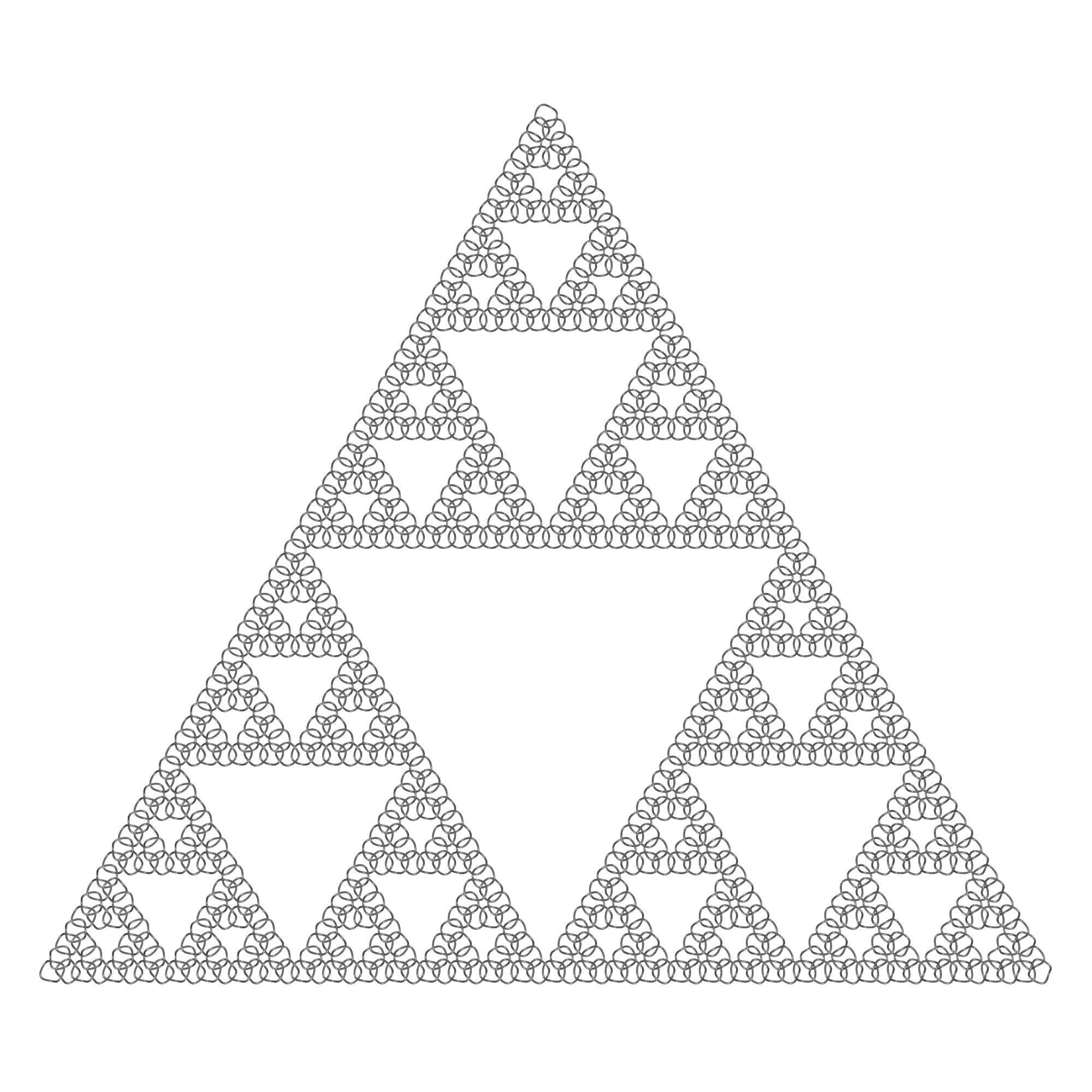
Created out of Borromean rings, Sierpinski chainmail.
Sierpinski carpet
Closely related to the gasket is the Sierpinski carpet. Instead of removing the central third of a triangle, the central square piece is removed from a square sliced into thirds horizontally and vertically. As with the gasket the area tends to zero and the total perimeter of the holes tend to infinity.
The dimension of the carpet is log 8 / log 3 = 1.8928. Note that any line between two adjacent vertices of the gasket is a triadic cantor set.
Sierpinski Gasket in 3 Dimensions
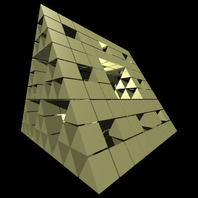
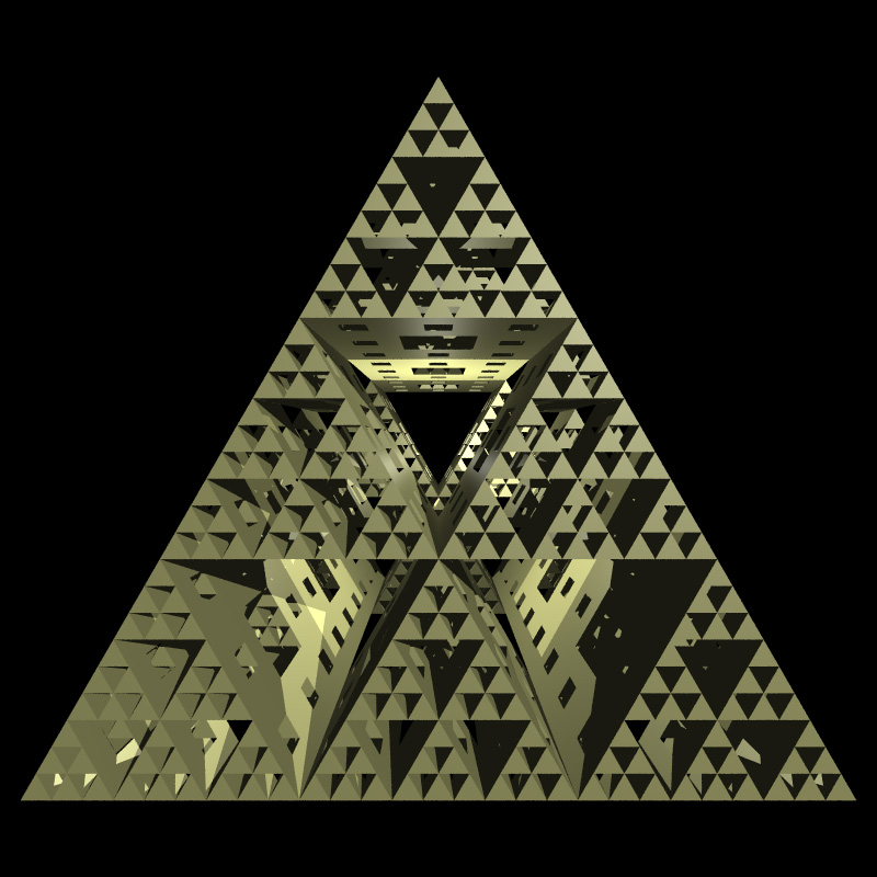
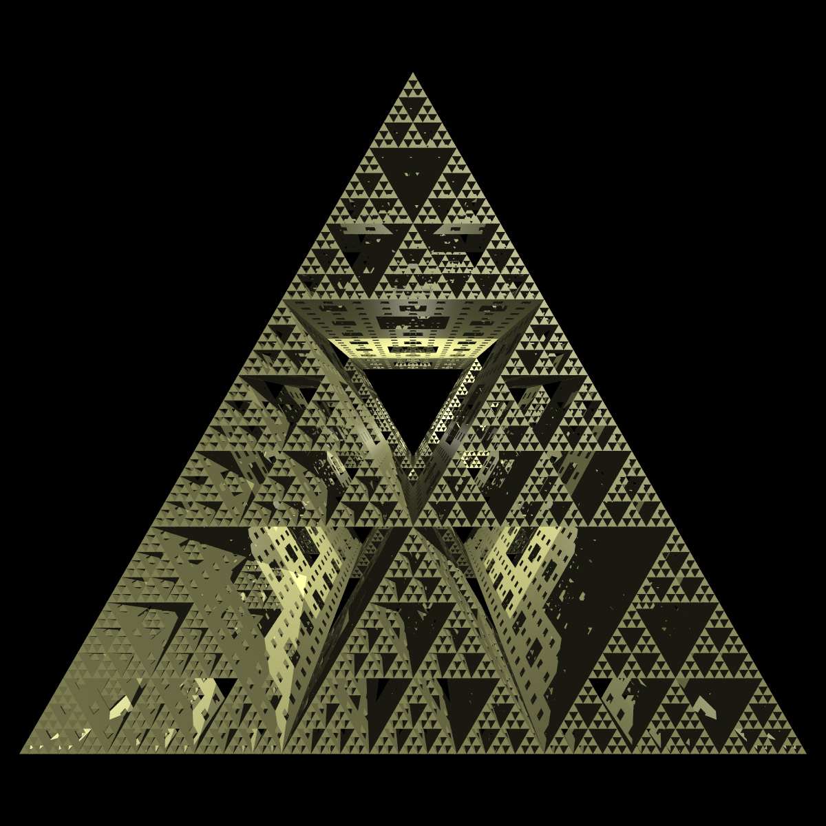
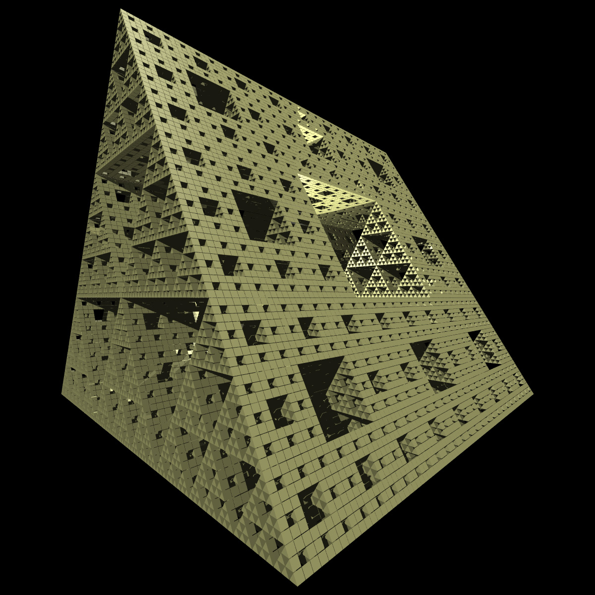
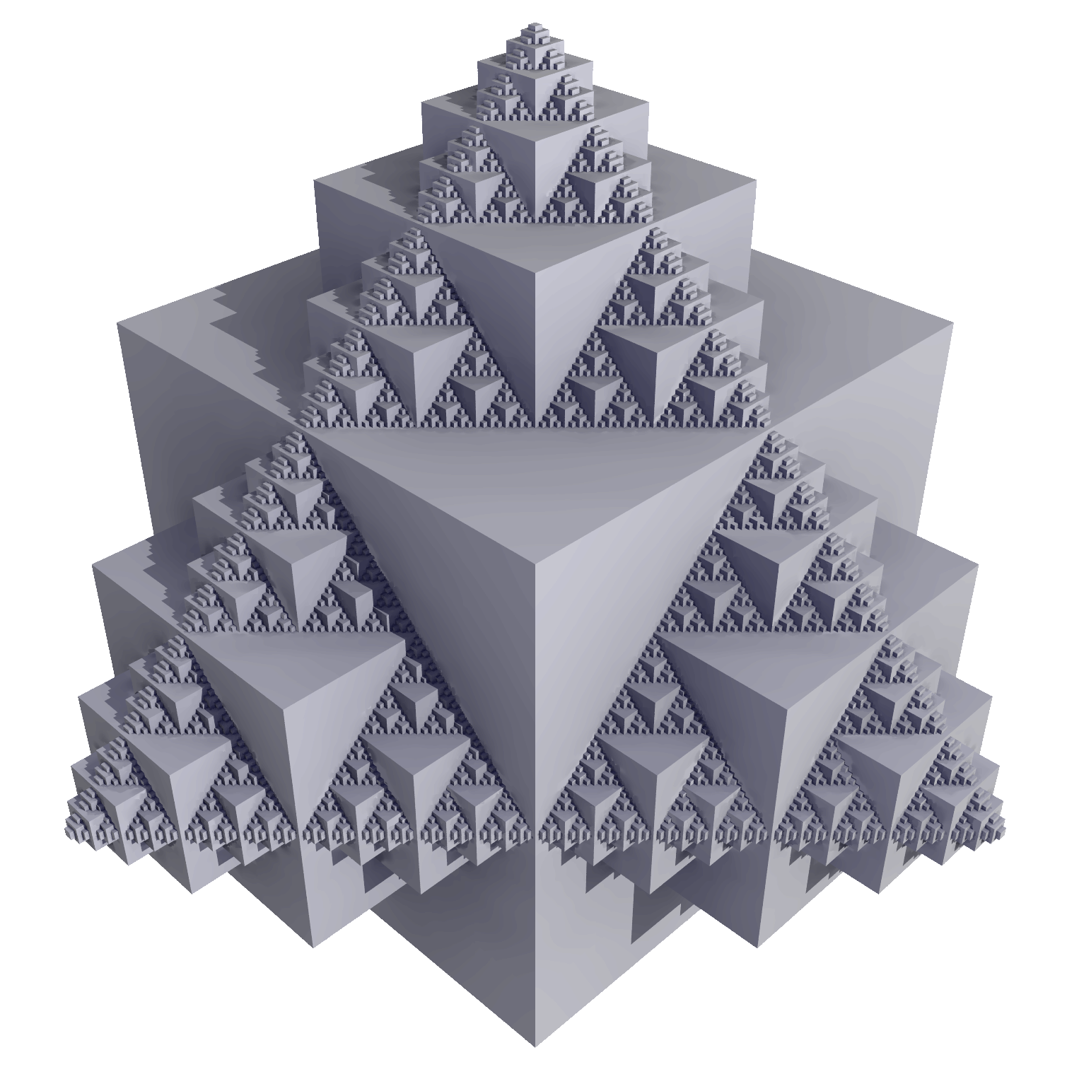
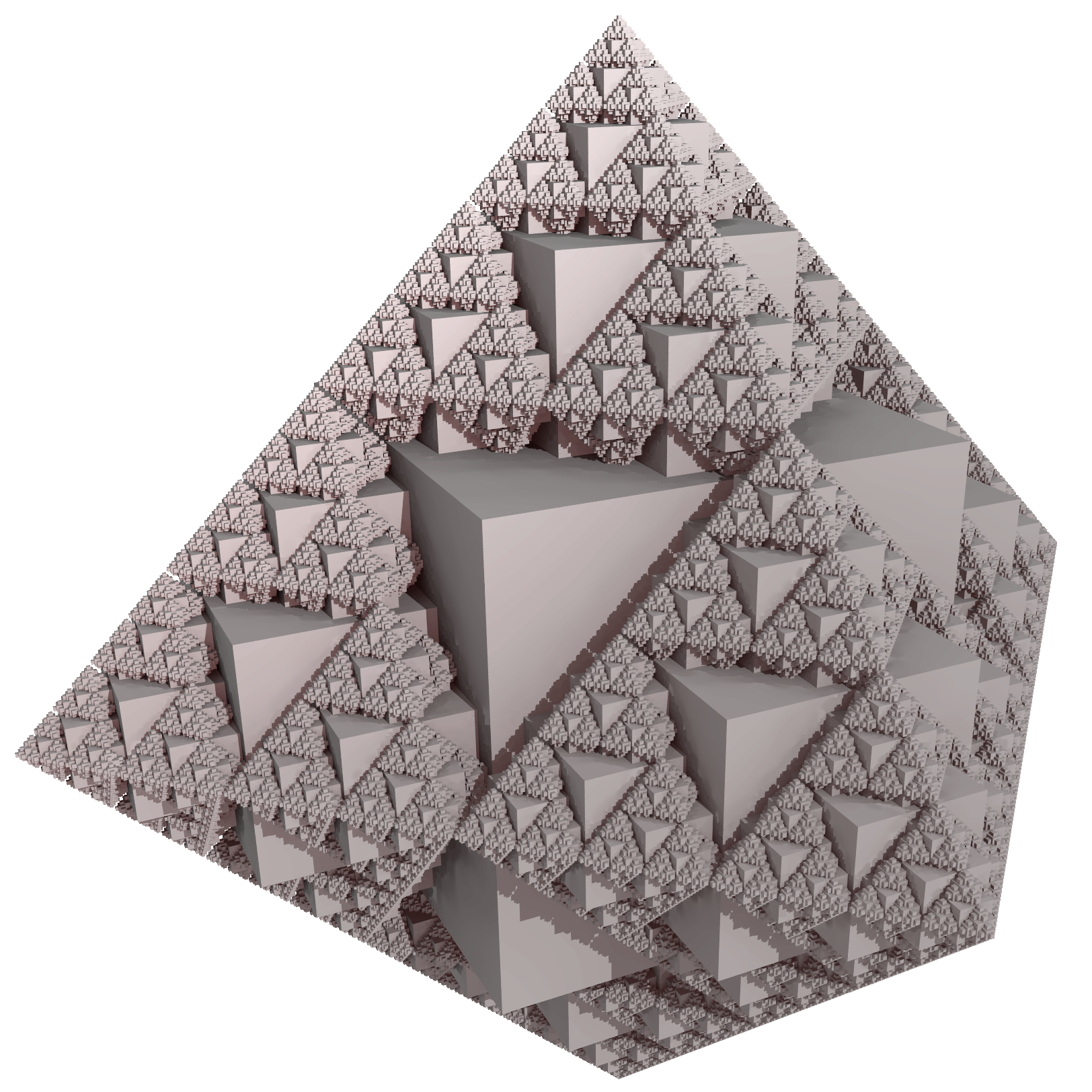
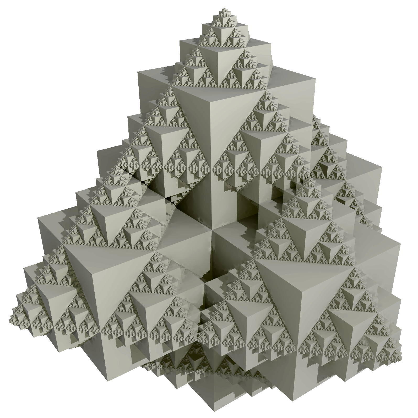
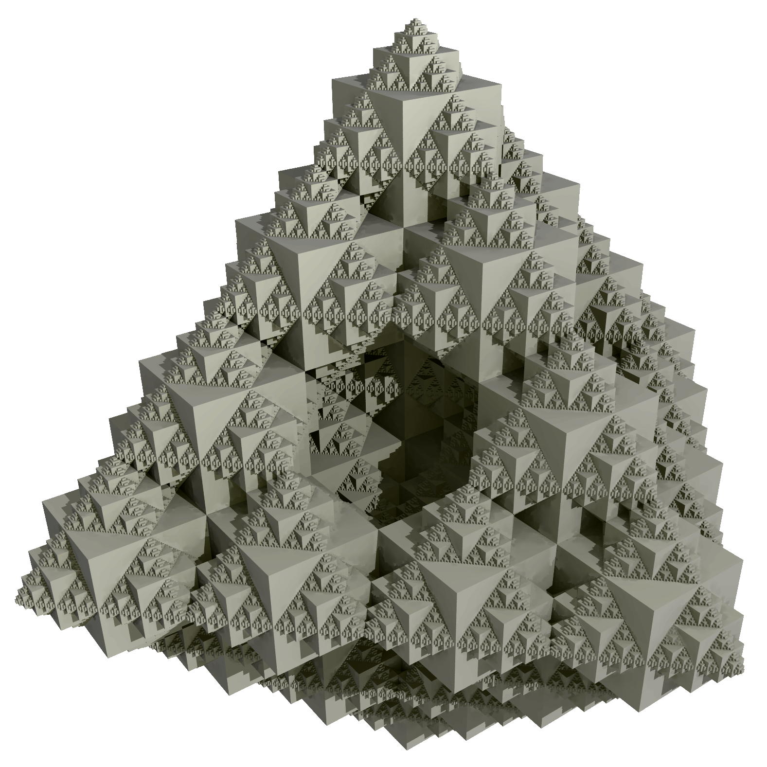
The construction of the 3 dimensional version of the gasket follows similar rules for the 2D case except that the building blocks are square based pyramids instead of triangles. The generator is illustrated below, on each successive iteration the pyramids are replaced by a scaled version of the generator.
In comparison with the 2D case the 3D gasket is an object with zero volume but a constant surface area. As a storage method this must surely be a packers nightmare, it takes an finite amount of packaging material to store nothing. The four side faces of the 3D gasket are 2D gaskets. The dimension is log 5 / log 2 = 2.3219 Menger sponge
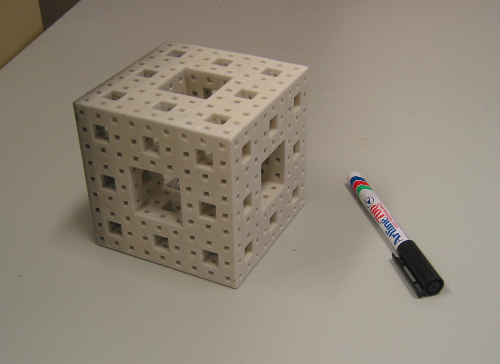
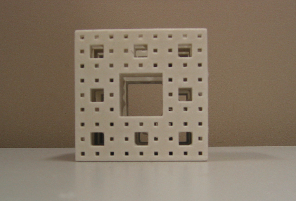
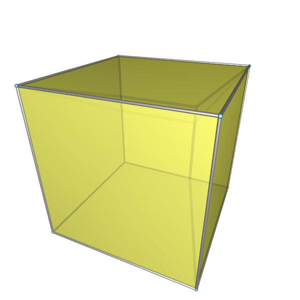
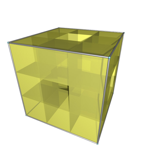
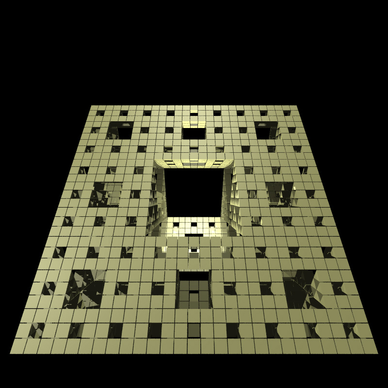
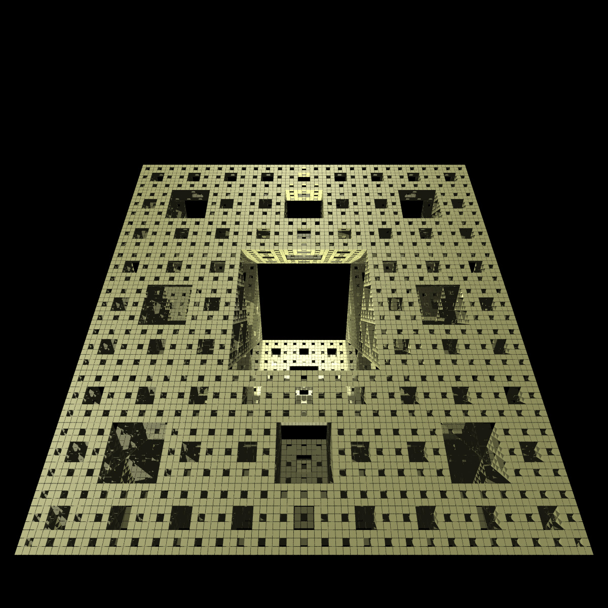
The sponge is the 3 dimensional form of the 2D carpet. It is created by sectioning the unit cube by slits of width 1/3 as shown by the generator below. The central piece and each cube located at the center of the faces are removed. This process is repeated forever with the resulting cubes.
Each face of the sponge is a carpet. Intersections of the sponge with mediums or diagonals of the initial cube are triadic Cantor sets. Dimension = log 20 / log 3 = 2.7268 HyperGasket
By following the procedure of creating a gasket in the 2nd and 3rd dimensions it is possible to do the same thing in higher dimensions, in particular the 4th dimension. All that we need is the equivalent of the pyramid in the 4th dimension (normally the name pyramid is given to the 3D square base pyramid, a 2D pyramid is an equilateral triangle, and a 1D pyramid is a line segment). The intuitive method of determining the geometry of a 4D pyramid is to determine how a pyramid is defined in the lower dimensions. In 2D the pyramid is constructed by taking a line segment (1 dimensional cube) and pulling the midpoint into the 2nd dimension.
The 3D pyramid is constructed by taking a square (2 dimensional cube) and pulling the midpoint into the 3rd dimension.
The procedure then for creating an N dimensional pyramid can be summarized by the following rules
Using these rules the 4D pyramid (hyper-pyramid) is constructed by taking a 3D cube and pulling its midpoint into the 4th dimension.
To form a 4D gasket the hyper-pyramids are arranged in the equivalent fashion to the 2D and 3D construction. In the first iteration the base contains 8 hyper-pyramids with one hyper-pyramid at the apex. On each iteration the number of hyper-pyramids increases by a factor of 9 so that the dimension is log 9 / log 2 = 3.17 The problem now becomes one of visualizing a structure that is so outside our normal geometric experience. One technique for visualizing a 3D object on a plane is to take slices along the 3rd dimension, this results in curves (2 dimensional) usually called contour lines. The impression of the 3D object is obtained by imagining the contour curves stacked along the axis of slicing. The essence of the technique is that an N dimensional object is illustrated with a stack of N-1 dimensional objects. The same technique can be applied to 4 dimensional objects, they are sliced along the 4th dimensional axis except now the result is a number of 3D objects, these could be called contour solids. These slices, each a 3D object, can be displayed and visualized with existing computer techniques to display 3D forms. Of course, as in the 3D situation the slices need not be taken perpendicular to one axes but they can be cut along any arbitrarily orientated plane. Source code
Radiance generators for the sponge and gasket STL models Built using a ZCorp Z406 rapid prototyping machine.
References
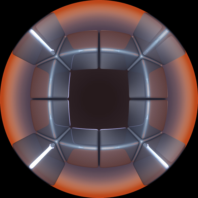
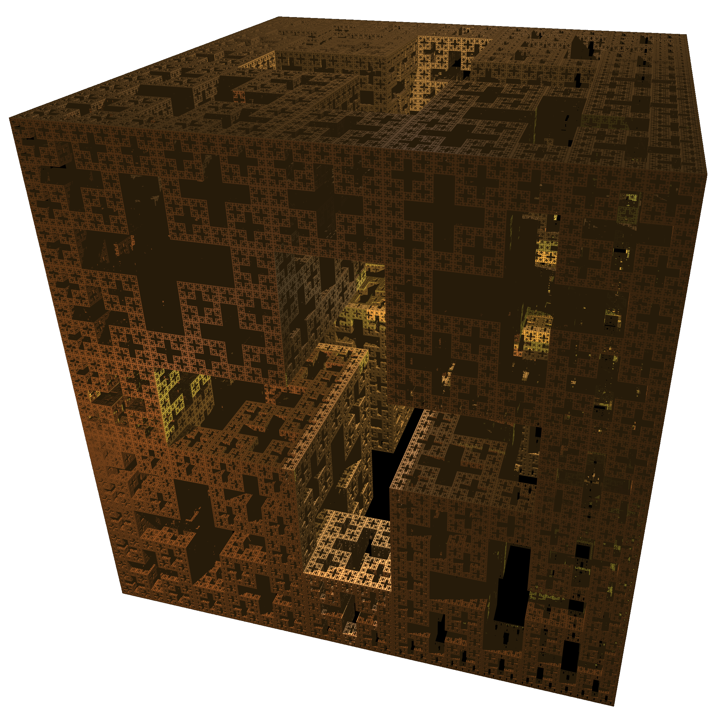
Menger Sponge by Angelo PesceRendered using MegaPovPlus on a Alpha (XP1000) Clusterby Paul Bourke June 2001
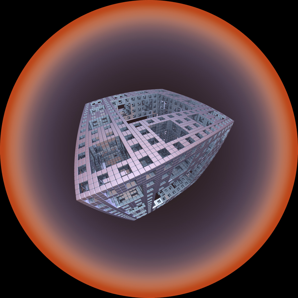
In 1926 when Karl Menger first looked at his creation, the Menger sponge, could he have ever imagined that in the future people would instruct machines to draw the sponge to depths he could only dream of. Some of these images would be created not for only for mathematicians but for a general audience and even for aesthetic appreciation. The following example was created by Angelo Pesce employing radiosity based rendering, space based colour, and an interesting distorting lens. 
The Menger sponge is the 3D equivalent of the Sierpinski carpet which is in turn the 2D equivalent of the 1D Cantor set. The Cantor set is formed by starting with a line segment. For the first iteration remove the middle third of the line. On each subsequent iteration the middle third of each line segment is removed. The remaining points after doing this an infinite number of times is called the Cantor set. 4 iterations towards this are illustrated below.  The 2D Sierpinski carpet is created by starting with a square, cutting it into 9 smaller squares and removing the central square. This process is repeated for each existing square "for ever", the first three iterations are shown below. (The resolution of your monitor prevents presentation of further iterations.) 
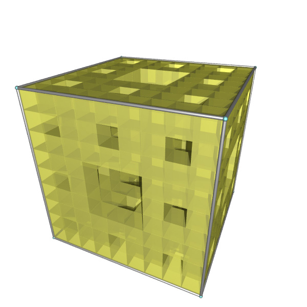
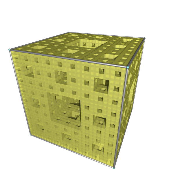
The 3D Menger sponge is created by performing a similar process on a cube. On each iteration split all cubes into 27 smaller equal size cubes. Remove the cube in the center of each side as well as the center of the original cube. Repeat this process for ever, the first few iterations are shown below. As with most fractals we can only ever create an approximations to the ideal fractal form. The Menger sponge in its final form (unlike the approximations we can create) has zero volume but an infinite surface area. Question : What would you see if you had an ideal Menger sponge? Would you see anything at all? 
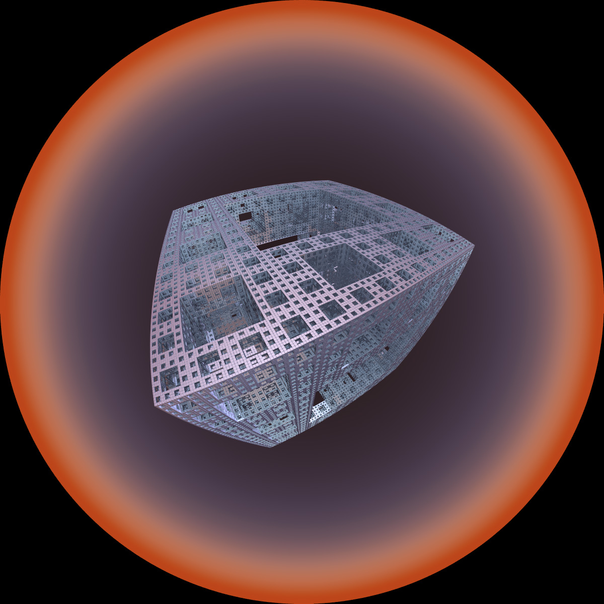
The Menger sponge is often used as a challenge to the computer graphics community. The amount of geometry required to render the sponge increases rapidly as the iteration depth increases. Using a brute force method the number of primitives required increases by a factor of 20 on each iteration. In other words if the first level is created with 20 boxes then the second level needs 400, the third 8000, the fourth 160000, and so on. This eventually exhausts the memory and computation power of any system. The sponge image above was created using MegaPovPlus, a derivation of PovRay. The following three files were used to create the image above: sponge.ini, sponge.pov, and sponge.inc. Beware, this rendering will take a significant amount of time on even the fastest machine. Some other renderings of the sponge by Angelo Pesce are shown below.
Files: mp_sponge2.ini, mp_sponge2.pov, mp_sponge2.inc
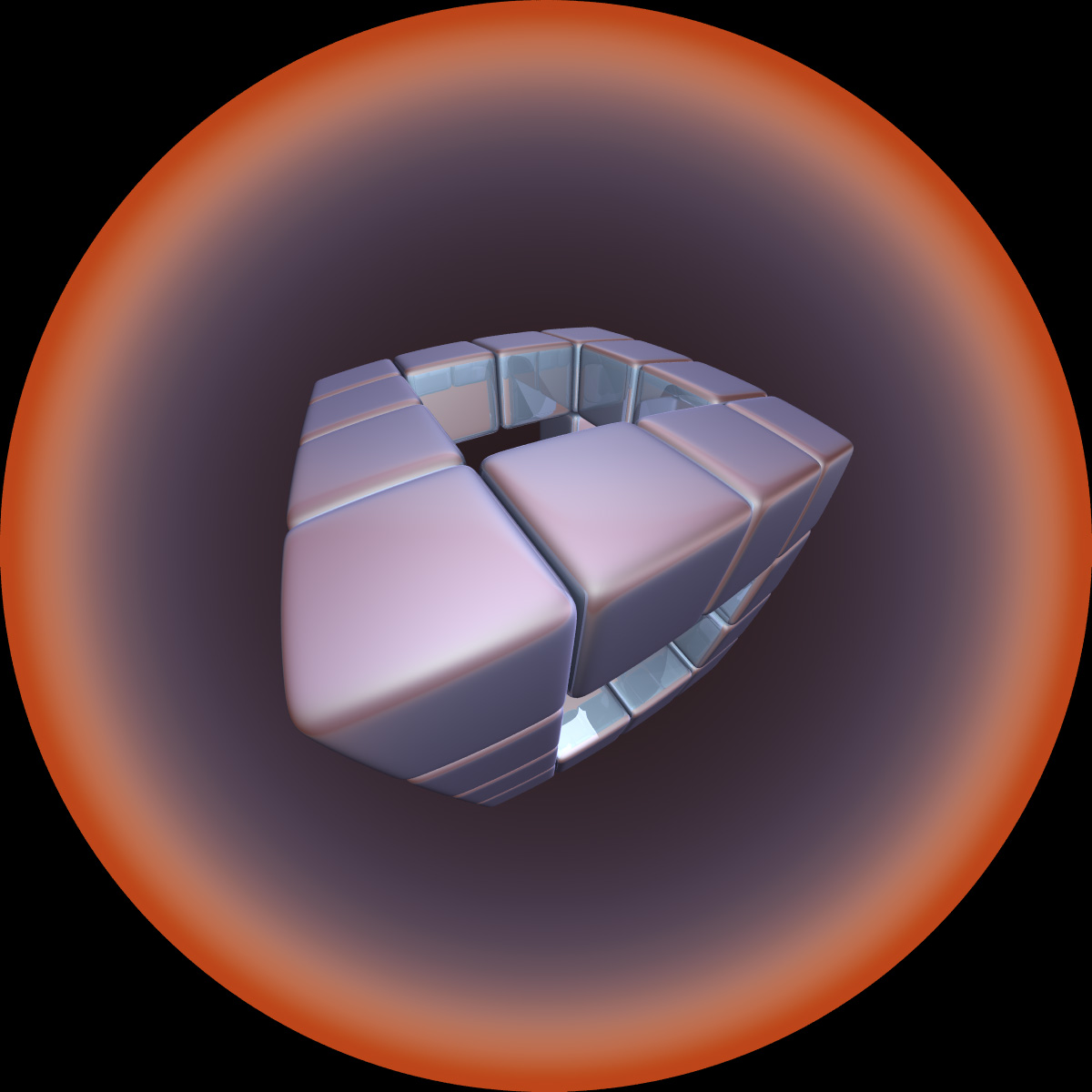
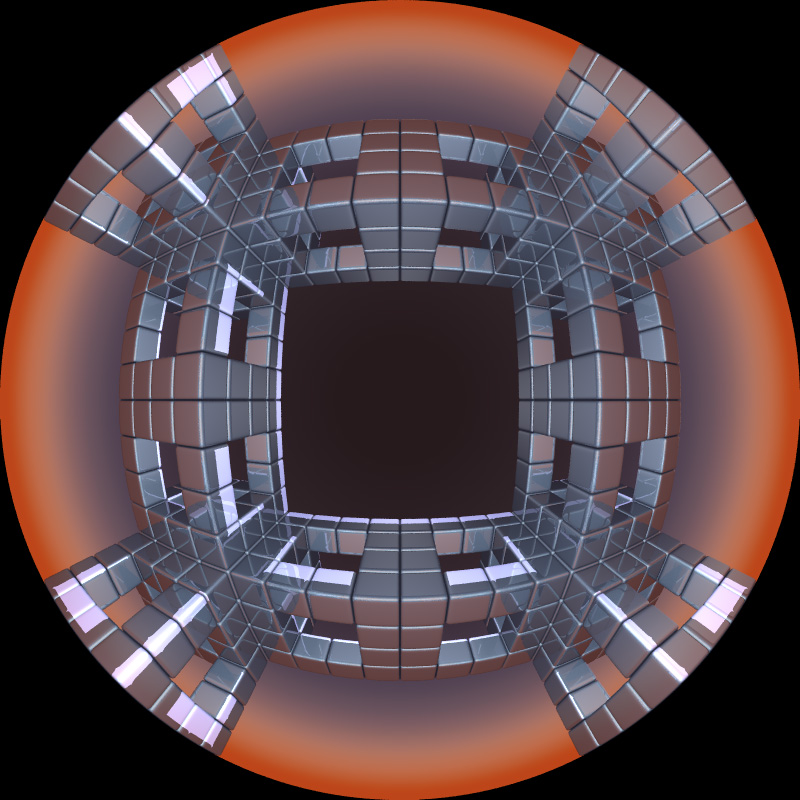
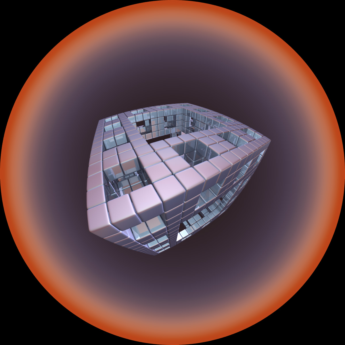
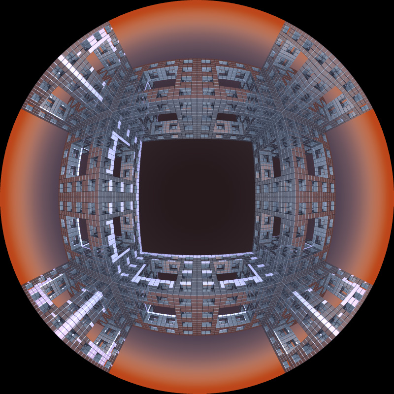
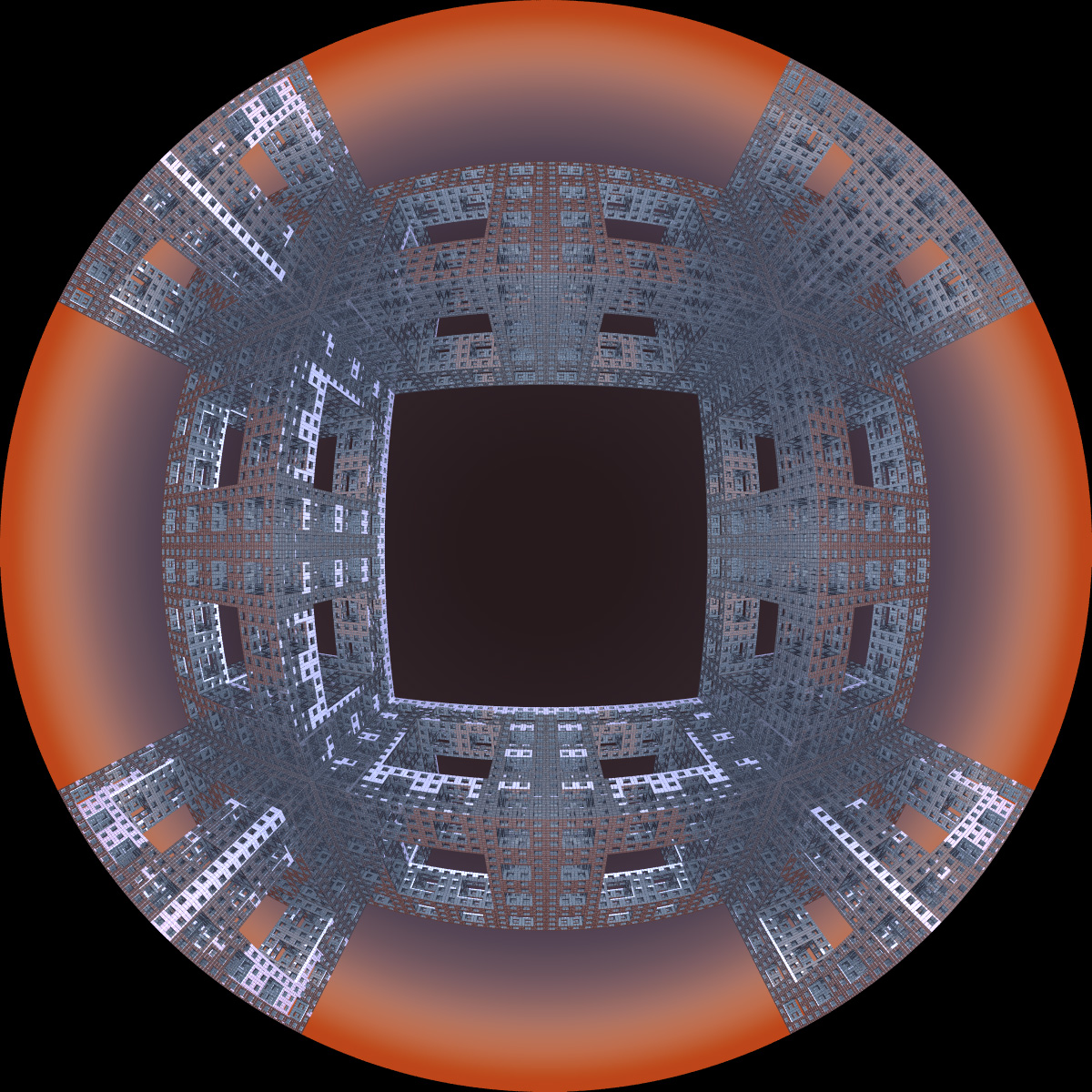
The following has the camera located at the center of the sponge and it uses a full spherical projection. 
Files: tri_sponge.ini, tri_sponge.pov, tri_sponge.inc
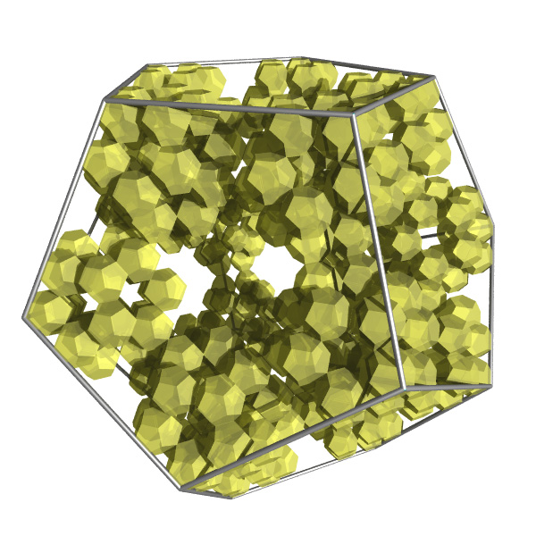
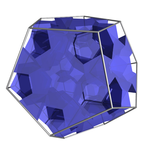
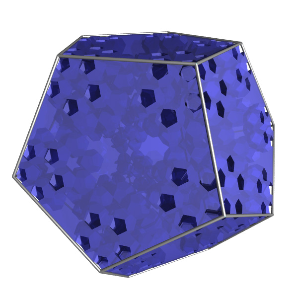
Platonic solid fractals and their complementsWritten by Paul BourkeInspired by Gayla Chandler December 2005
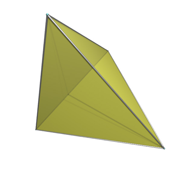
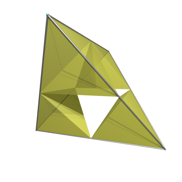
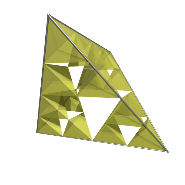
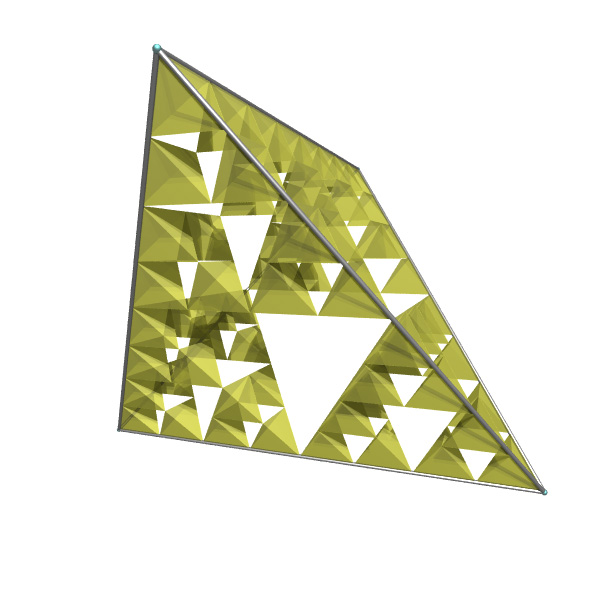
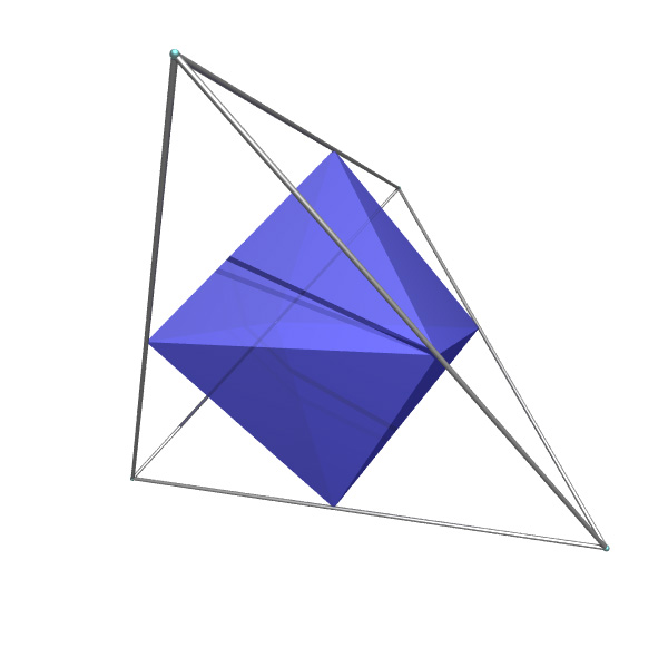
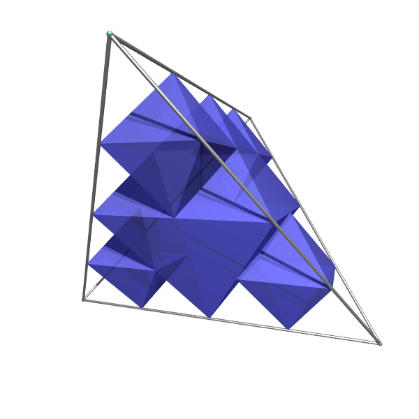
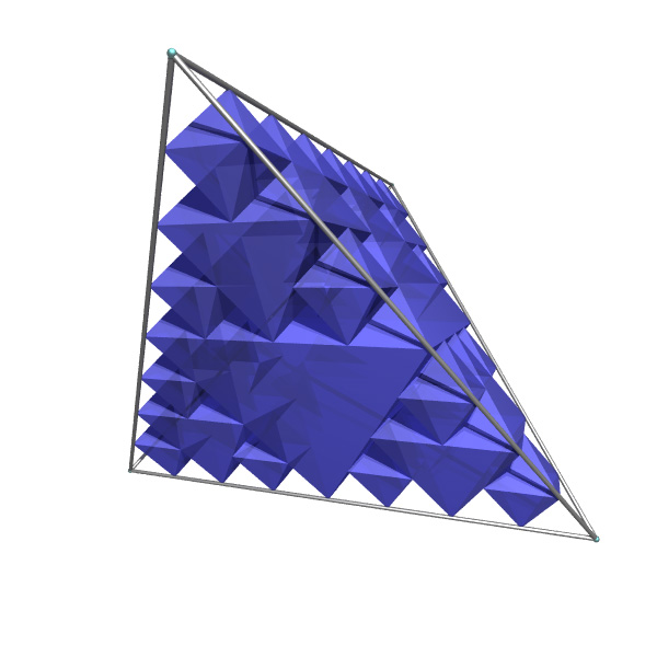
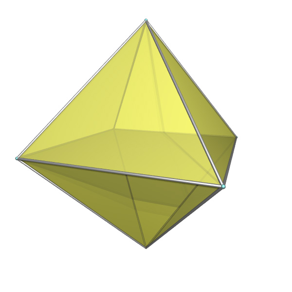
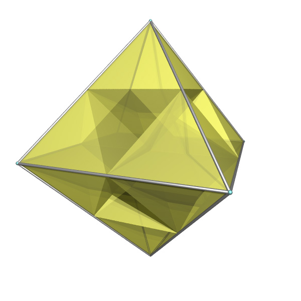
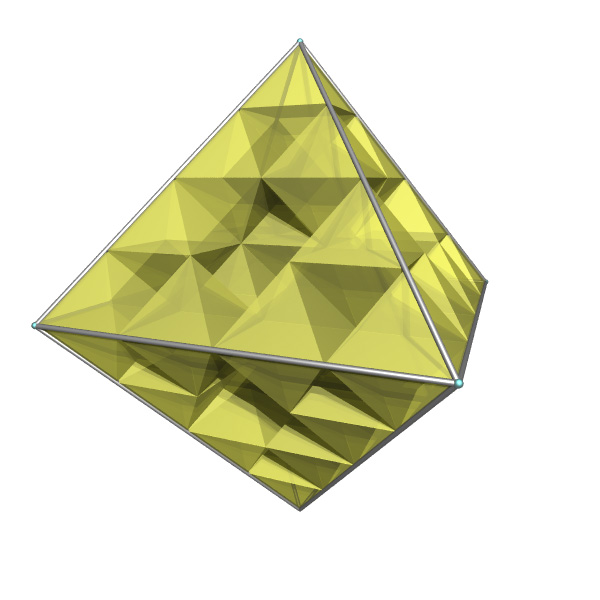
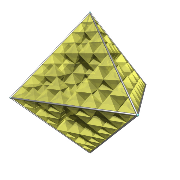
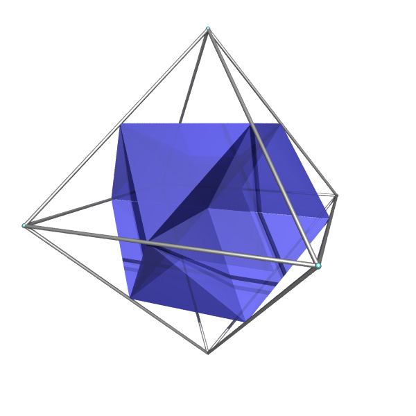
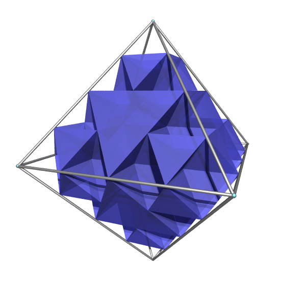
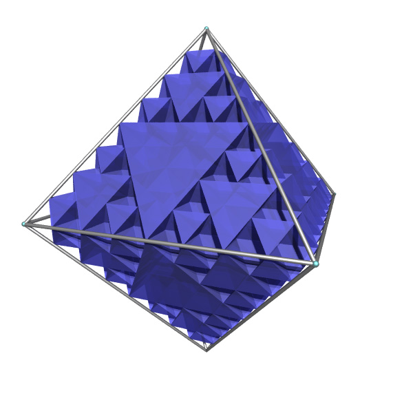
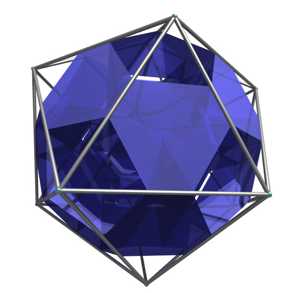
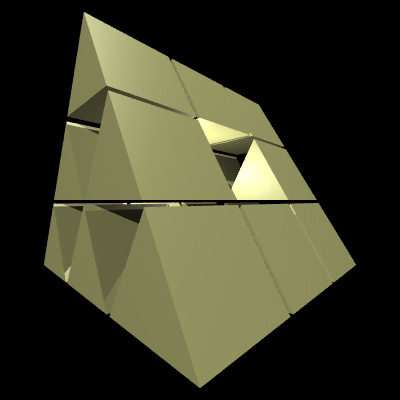
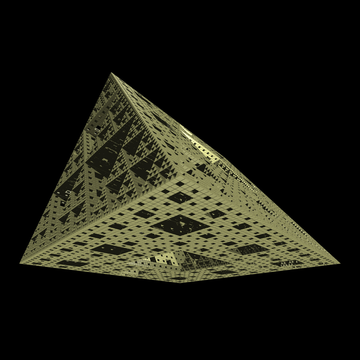
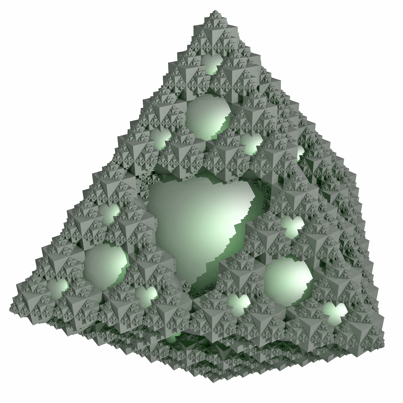
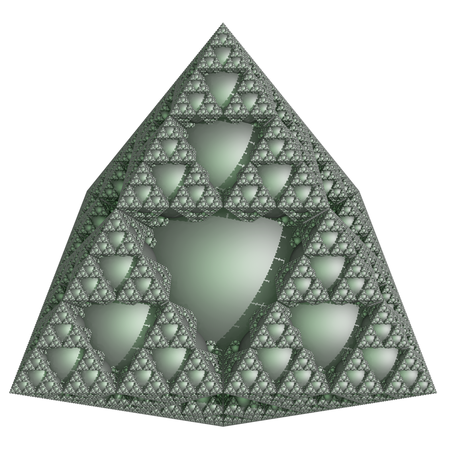
Illustrated here are fractals created using each of the platonic solids. Except for the special case of the cube, each fractal is created by positioning reduced versions of the platonic solid along the line from the center to each vertex of the solid. The exact reduction and the distance along the line is chosen so the final form is connected and the overall shape is the same as the seeding platonic solid. This procedure fails to give anything interesting for the cube so the Menger sponge is used instead. In addition the complement of each fractal is shown (in blue), that is, the fractal subtracted from the original platonic solid. The POVRay files are given for each form, render them with integer clock values from 0 upwards, the even numbered frames are the fractals, the odd numbered frames are the complements. Tetrahedron
Octahedron
Hexahedron
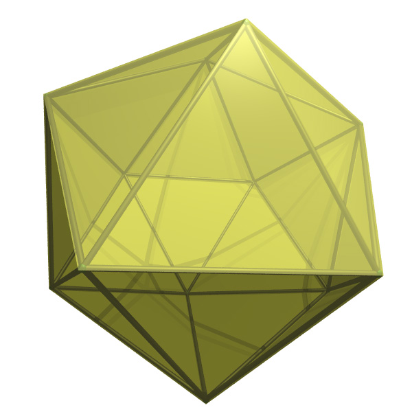
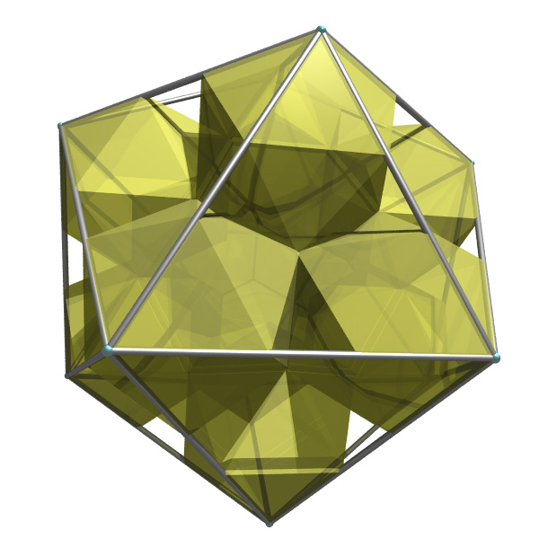
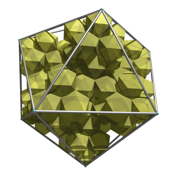
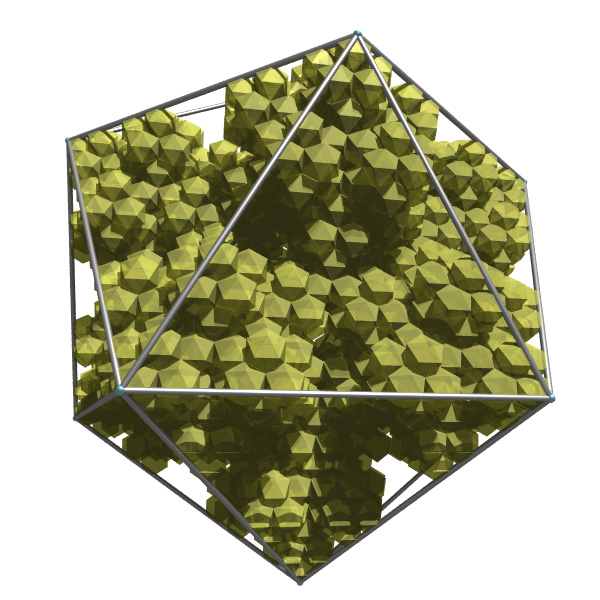
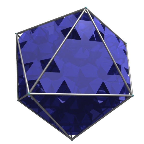
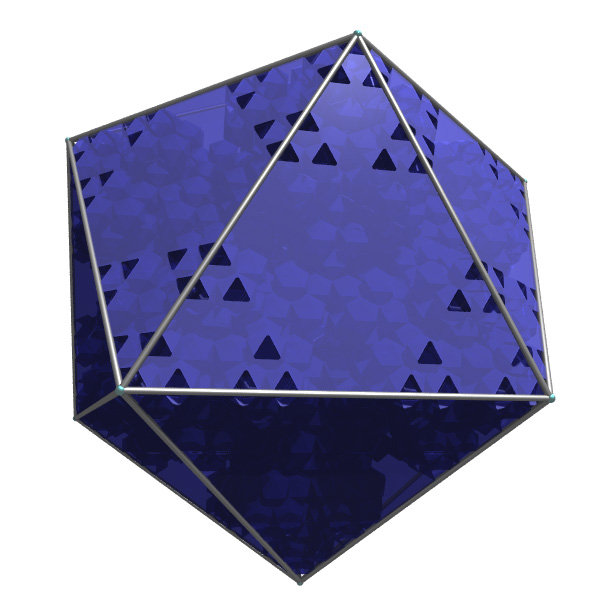
Icosahedron
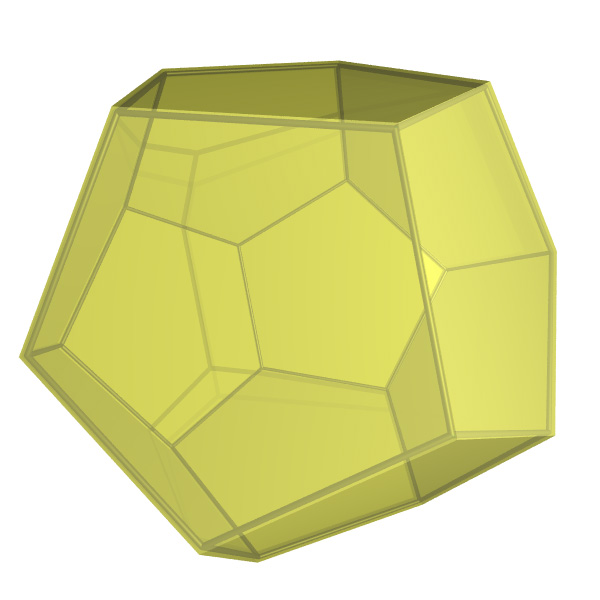
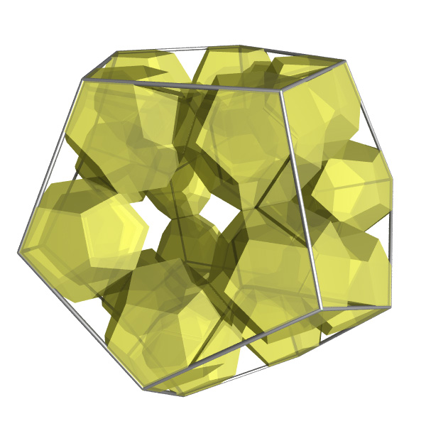
Dodecahedron
Variation to the tetrahedral case. 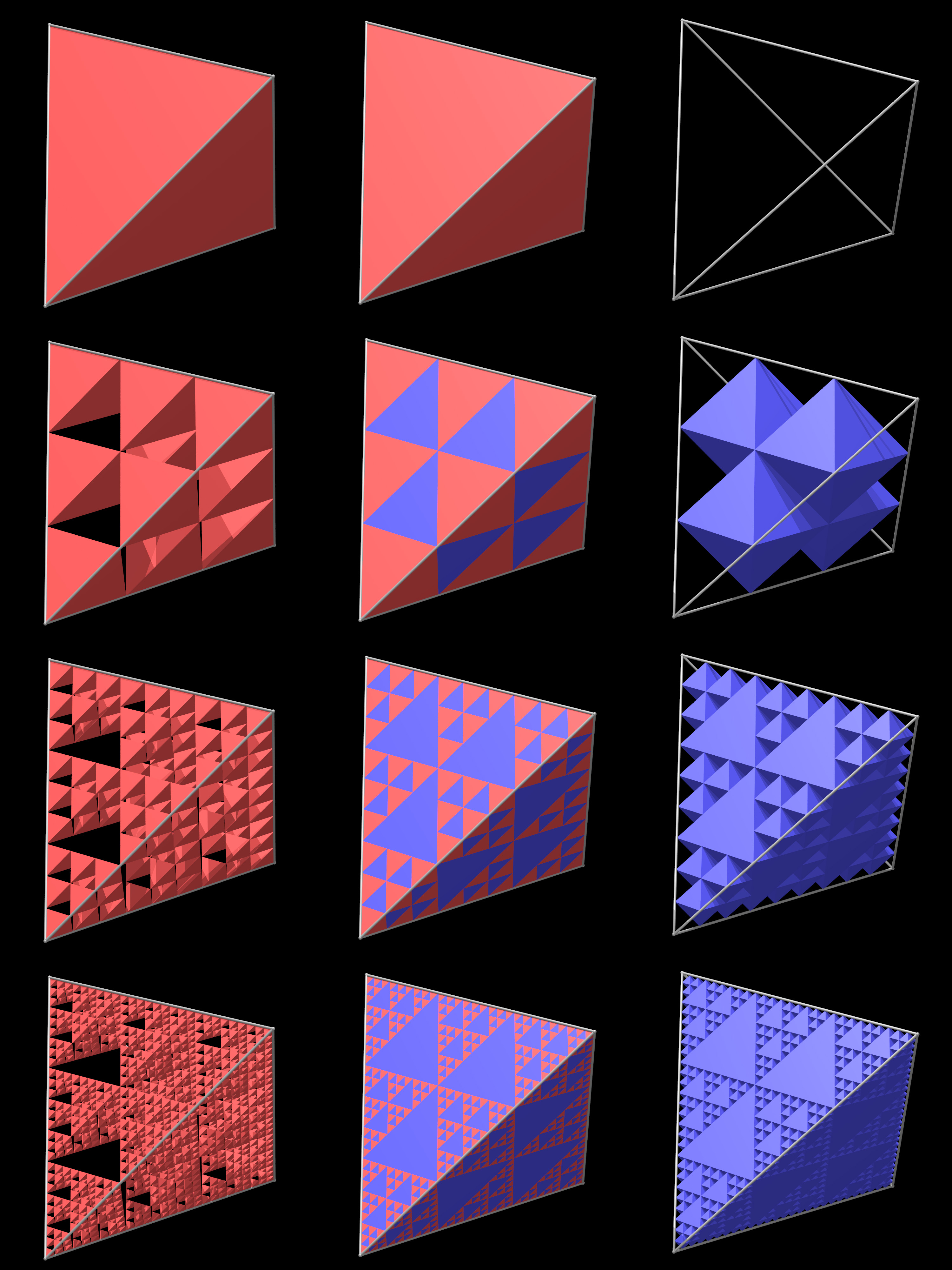
Boxed SetAttributed to Roger BagulaGraphics by Paul Bourke August 2007
A variation on the Menger sponge.
Crossed MengerAttributed to Roger BagulaGraphics by Paul Bourke August 2007
What do you get if you cross a Menger Sponge with the Sierpinski Gasket? Stage 1 and 2
Stage 3
Stage 4
Scale increases by a factor 3 on each iteration. PovRay scene file: scene.pov
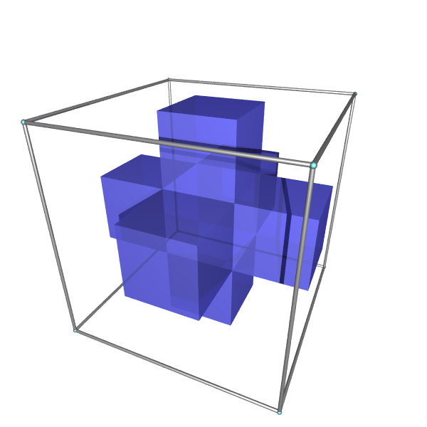
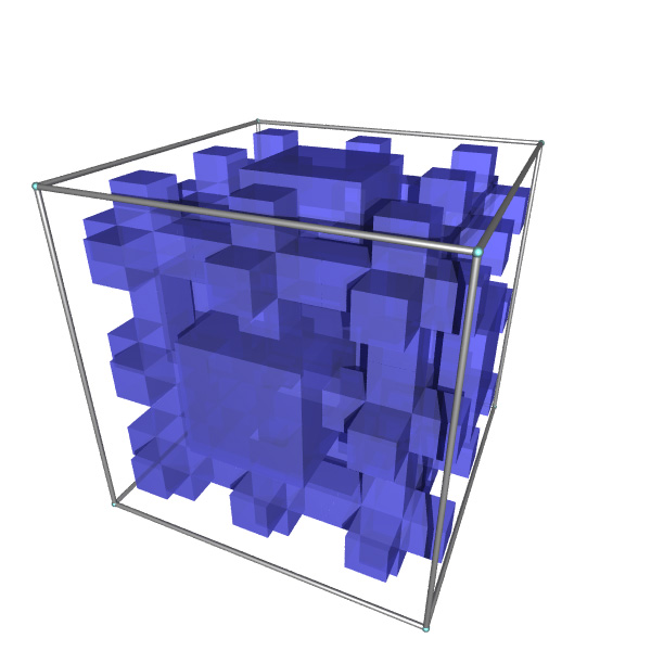
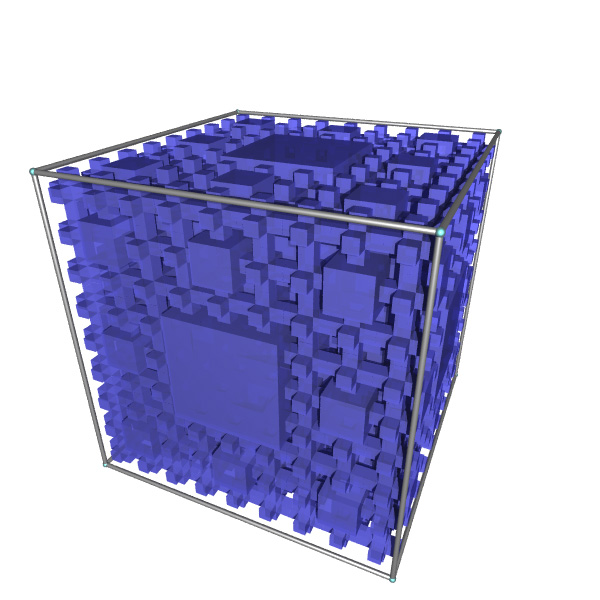
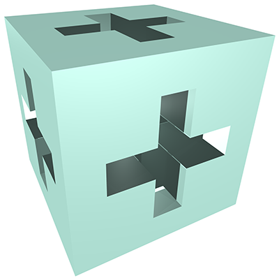
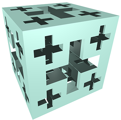
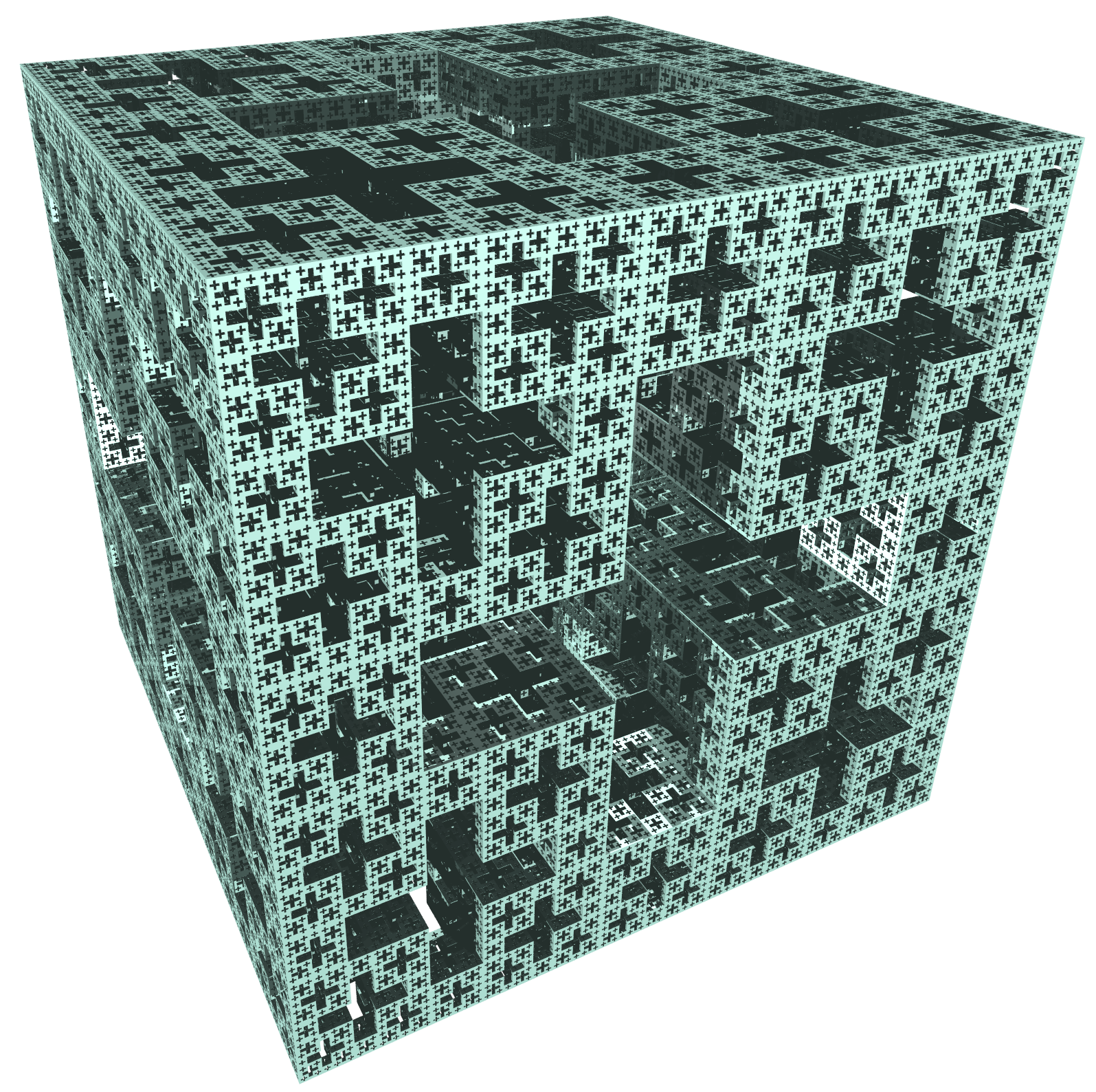
Jerusalem Menger CubeInspired by Robert DickauGraphics by Paul Bourke July 2014
Unlike the traditional Menger sponge this variation had irrational scaling on each iteration. If the zero'th iteration, a cube, is of unit 1 then the 8 corners of the Jerusalem Cube are cubes of side length sqrt(2)-1. The 12 smaller units are cubes of side length (sqrt(2)-1)2. This is the general scaling law to iterate from the n-1 iteration to the n'th iteration, noting (sqrt(2)-1) + (sqrt(2)-1)2 + (sqrt(2)-1) = 1.
Another way to imagine the construction is to repeatedly remove (negative extrusion) Greek crosses from the faces of a cube. Note the Greek crosses at each scale pass right through the final Jerusalem cube.
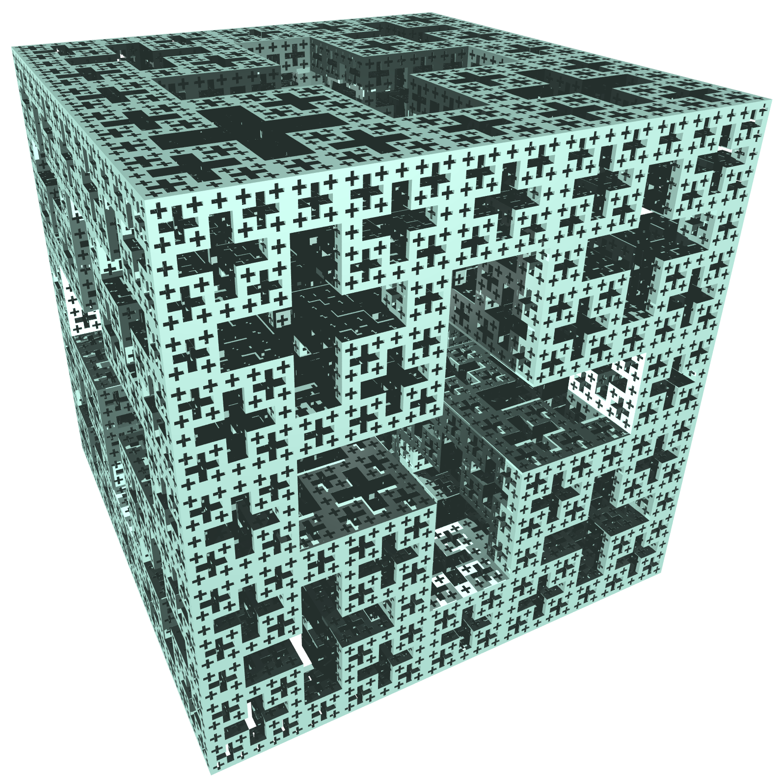
On each iteration the number of geometric primitives increases by a factor of 20, the same as the traditional Menger sponge. The compression ratio is sqrt(2)-1, the fractal dimension is 2.529 ...
Level 7 (Click for higher resolution)
Sample PovRay file: scene.pov
Cubic constructionGraphics by Paul BourkeJanuary 2018
Keplerian FractalsBased on work by Hop DavidComputer Generated Geometry and Rendering by Paul Bourke September 1998
Stellated Octahedron
 Iteration 8 Octahedron
 Iteration 4 | |||||||||||||||||||||||||||||||||||||||||||||||||||||||||||||||||||||||||||||||||||||||||||||||||||||||||||||||||||||||||||||||||||||||