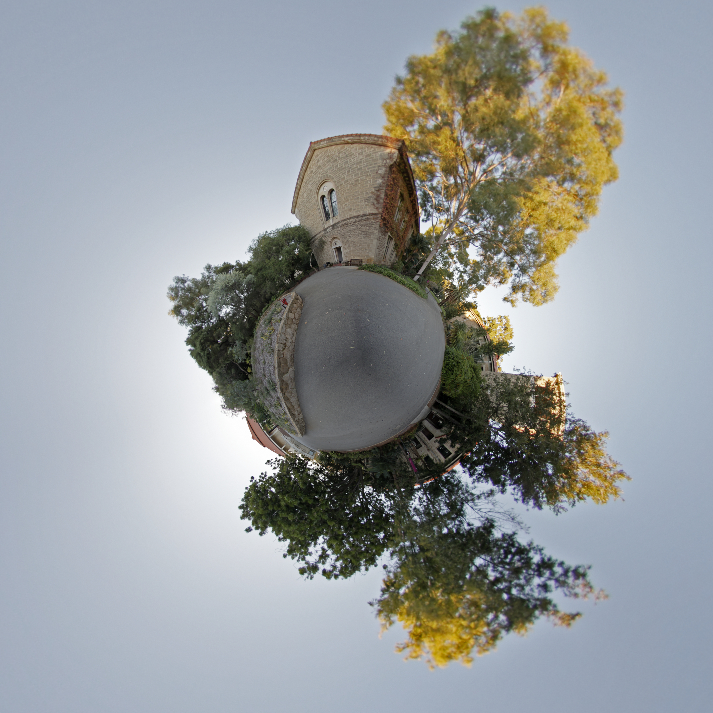
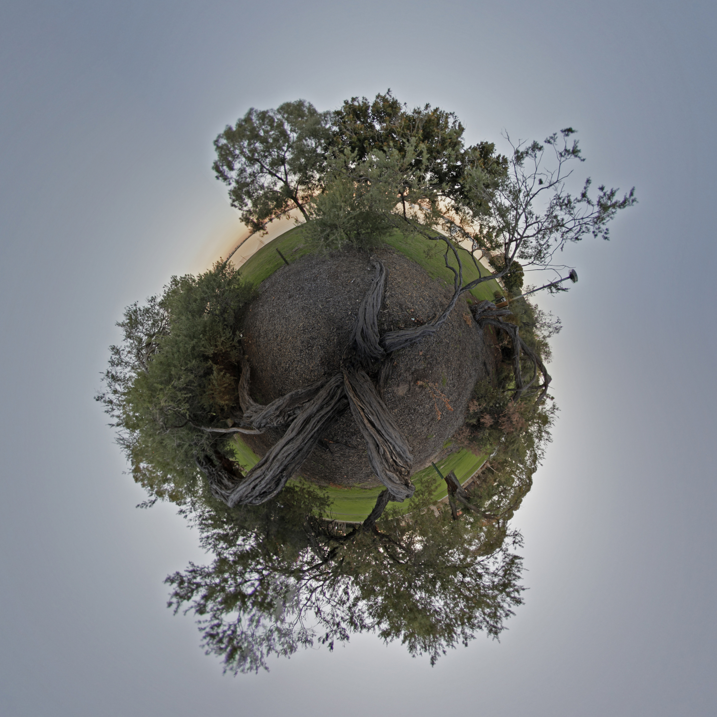
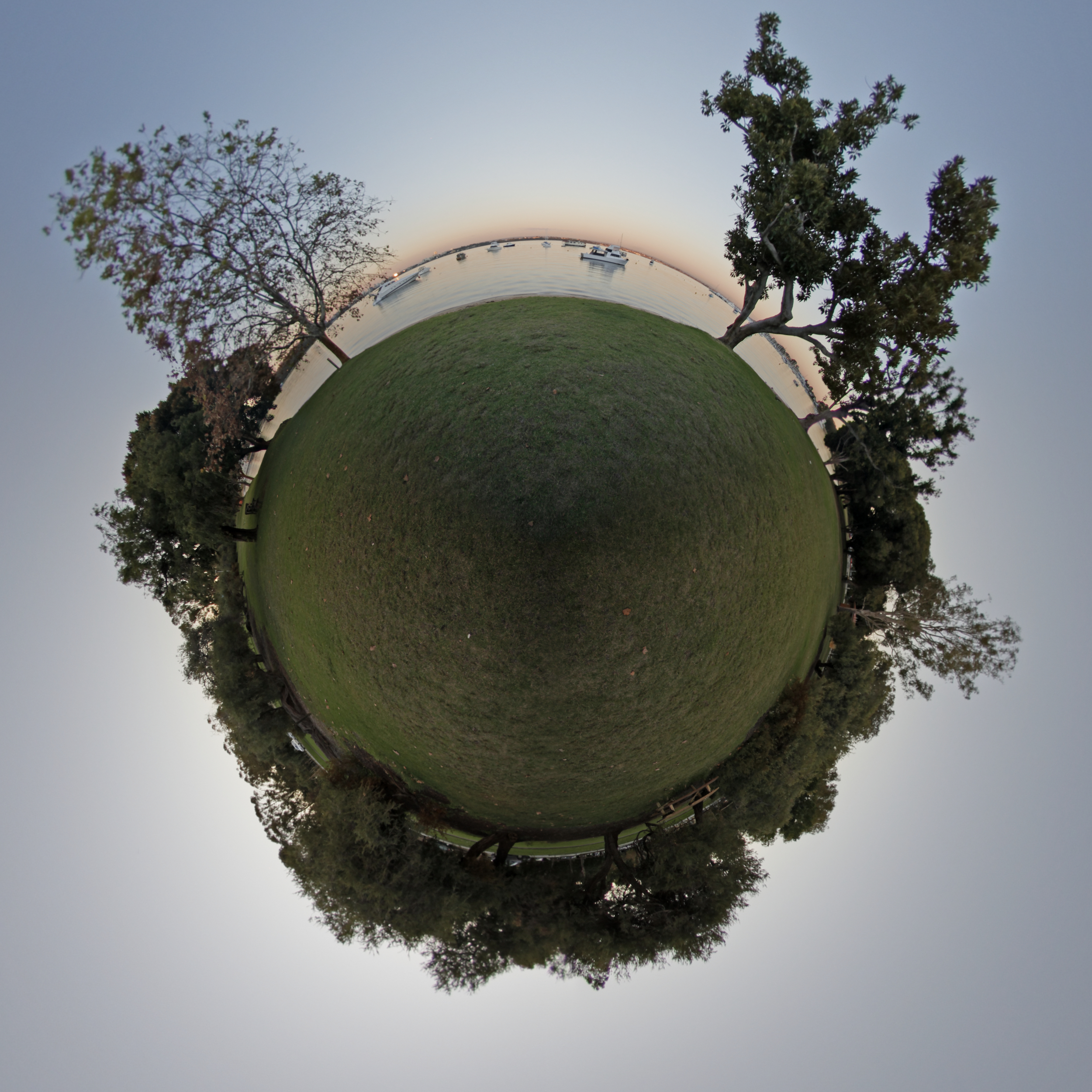
"Little Planet" PhotographsFrom the University of Western AustraliaPhotography by Paul BourkeMay 2011
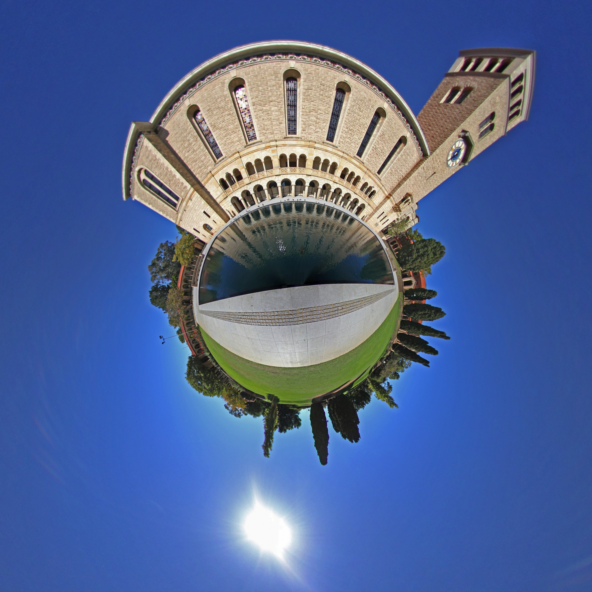
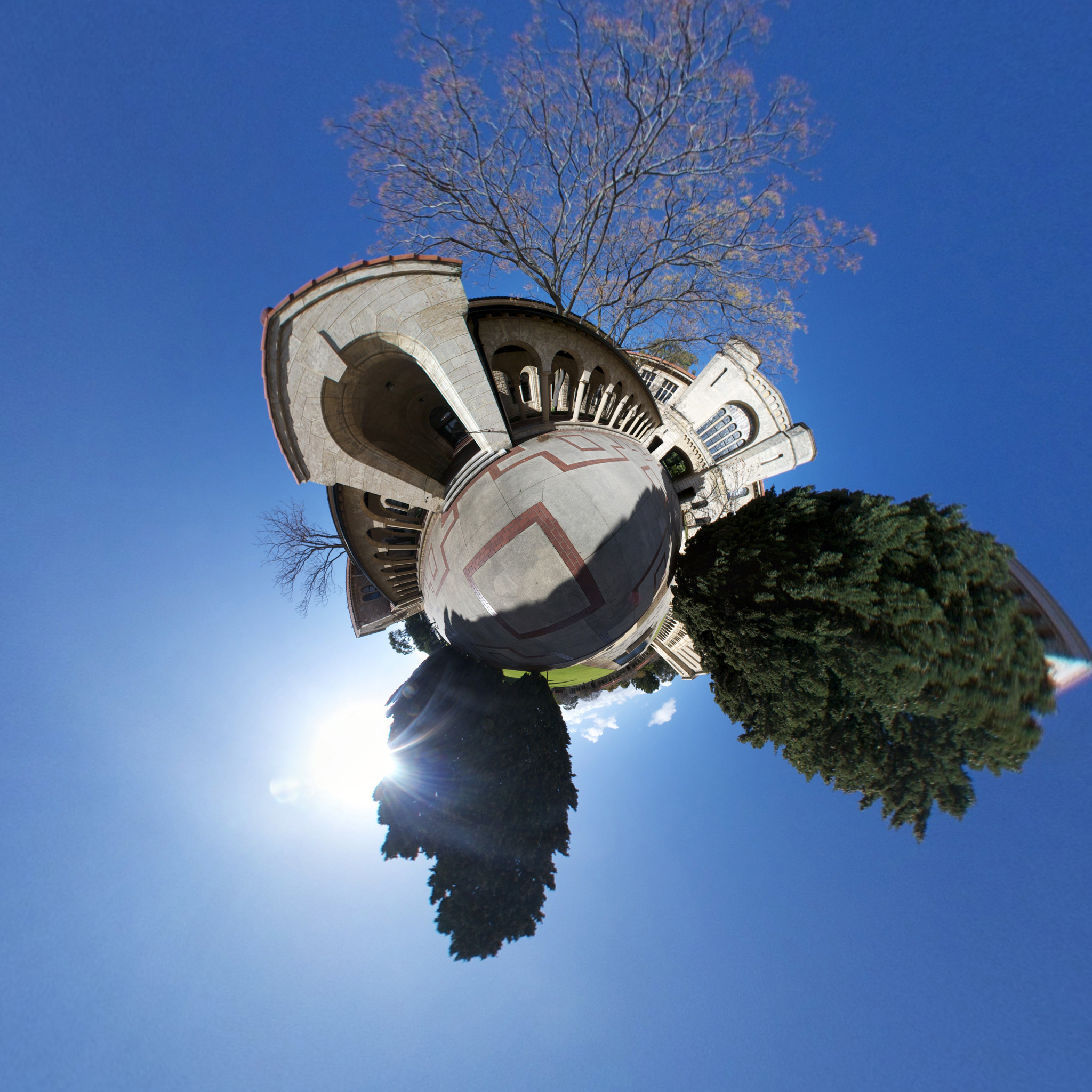
The source code implementing the projections below is only available on request for a small fee. It includes a demo application and an invitation to convert an image of your choice to verify the code does what you seek. For more information please contact the author. 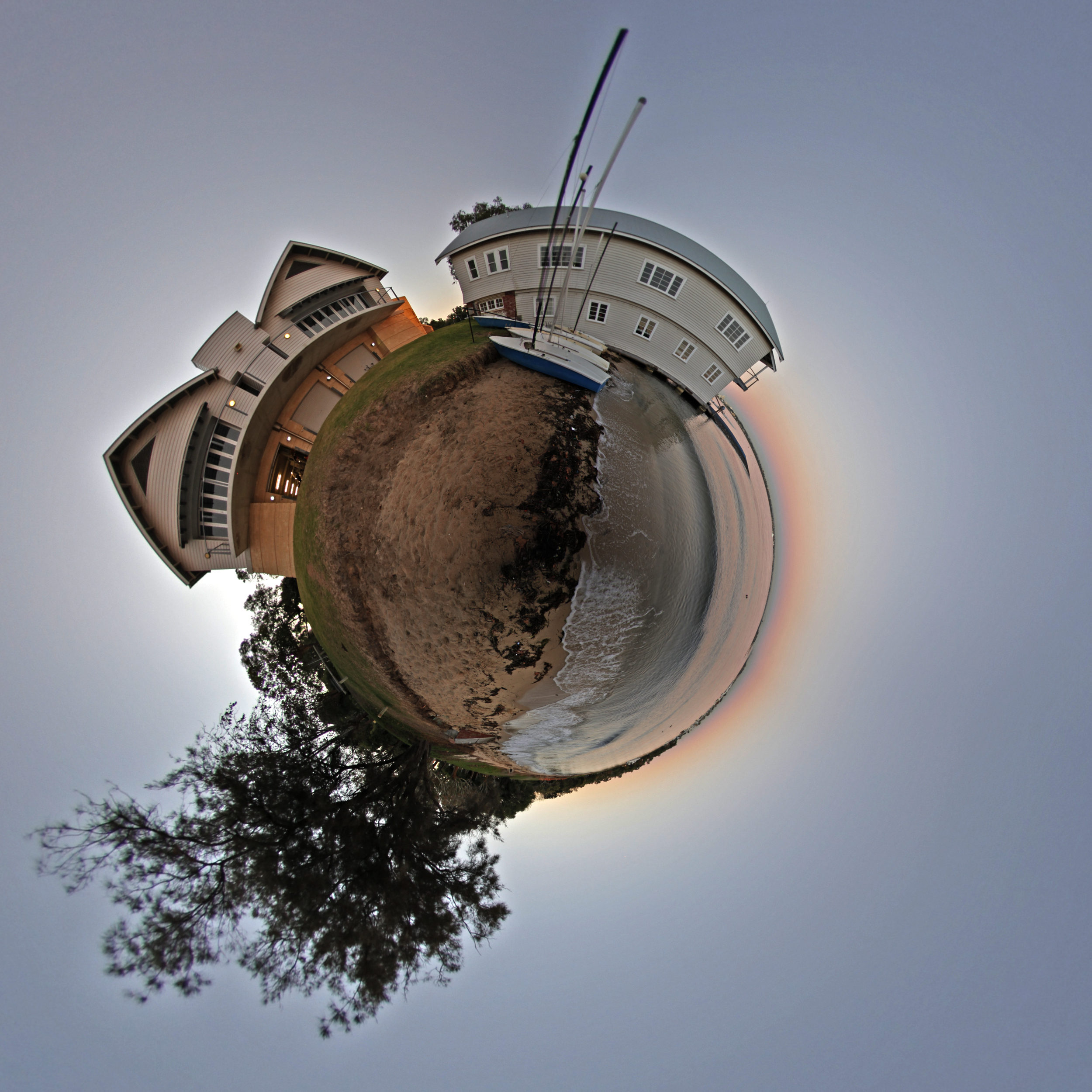 The making of ... and third place in the UWA Friends of the Grounds Photographic Competition, 2011.
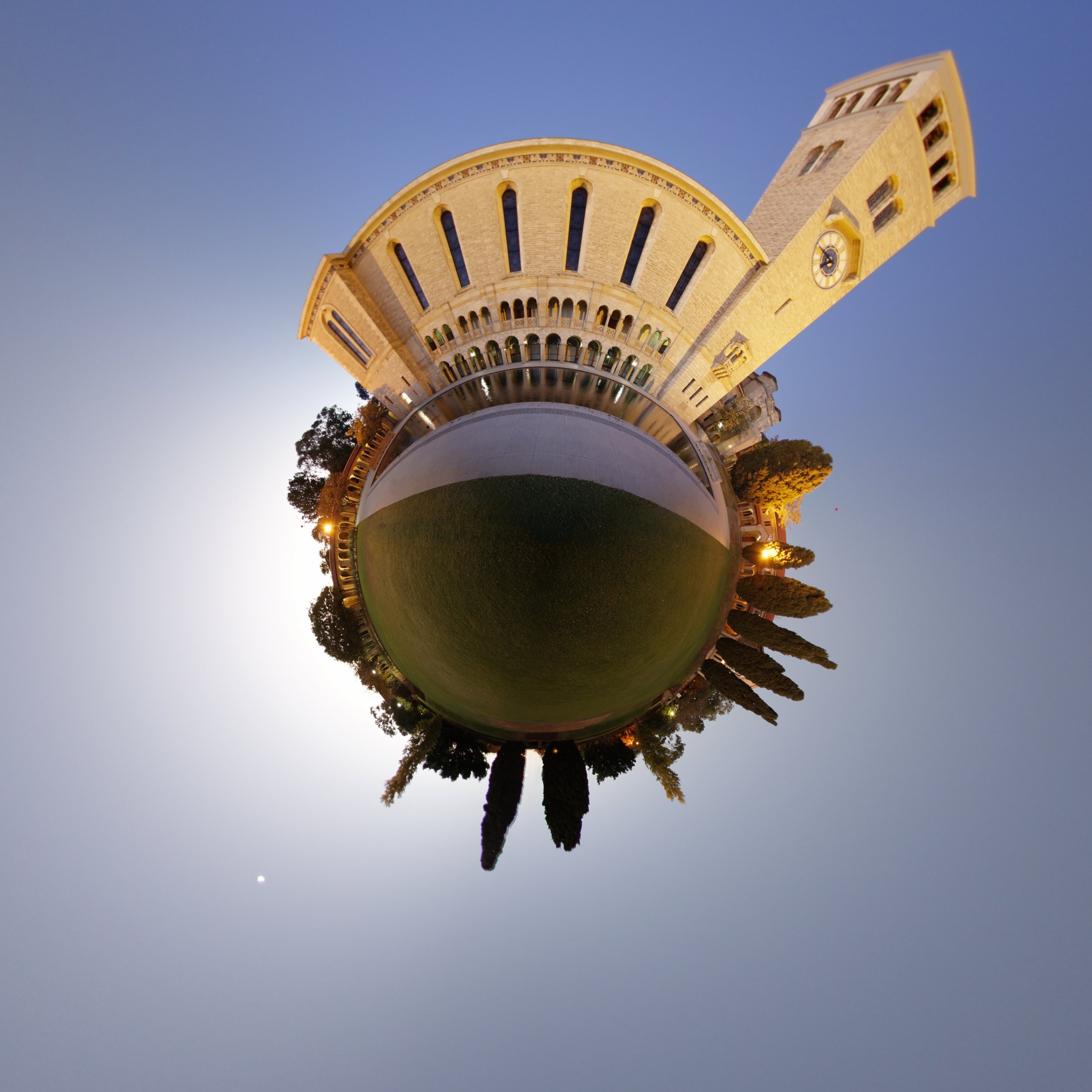
 Appears on the cover of the UWA Friends of the Grounds Calendar, 2012 Centenary edition and 2013 calendar.

Command line usage string. Usage: sphere2stereo [options] sphereimage Options -w n n width and height of the stereographic image, default = 512x512 -t n stereographic radius, default = 8 -a n antialiasing level, default = 2 -x n x axis panning rotate, default = 0 -y n y axis panning rotate, default = 0 -z n z axis panning rotate, default = 0 -o s output file name, name derived from input filename -h n height of nodal point, typically between 0 and 1, default: 1 -f n multiplicate fading, default: 1 (none) -r clip to unit circle, default: disabled The making of ...
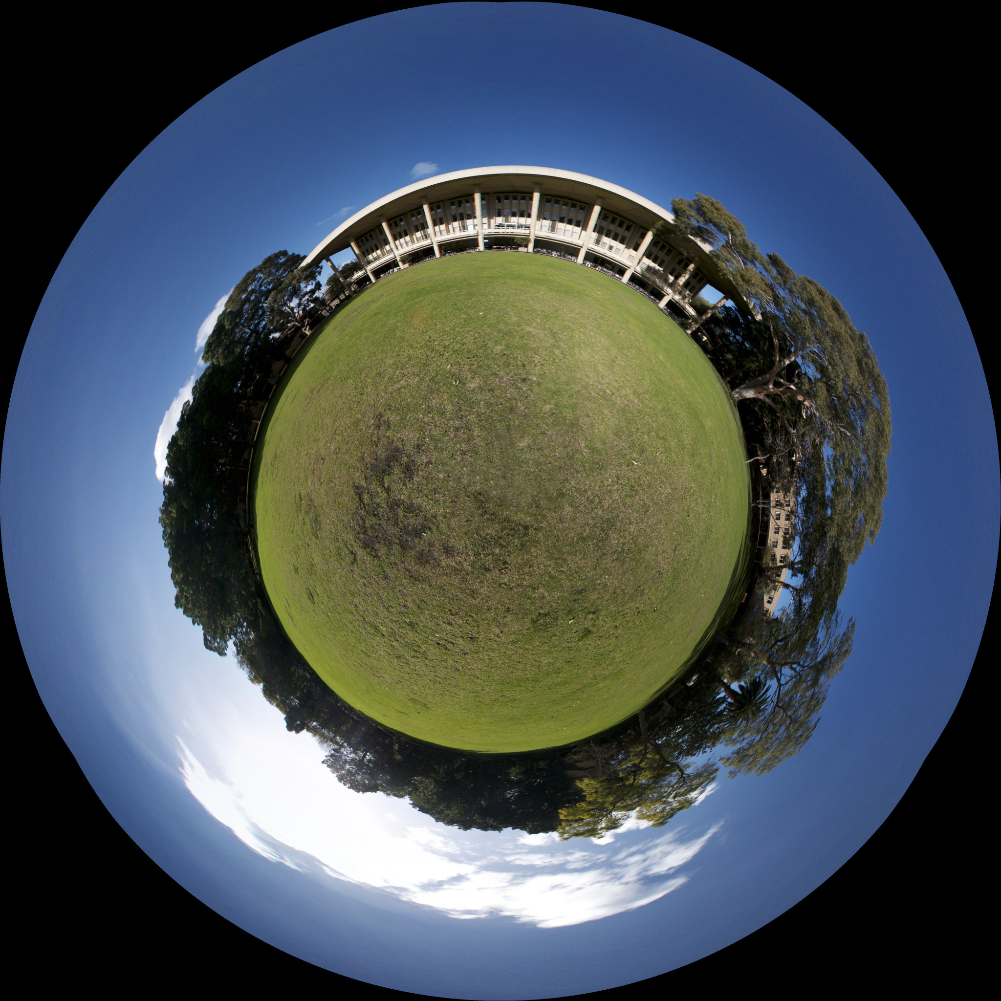
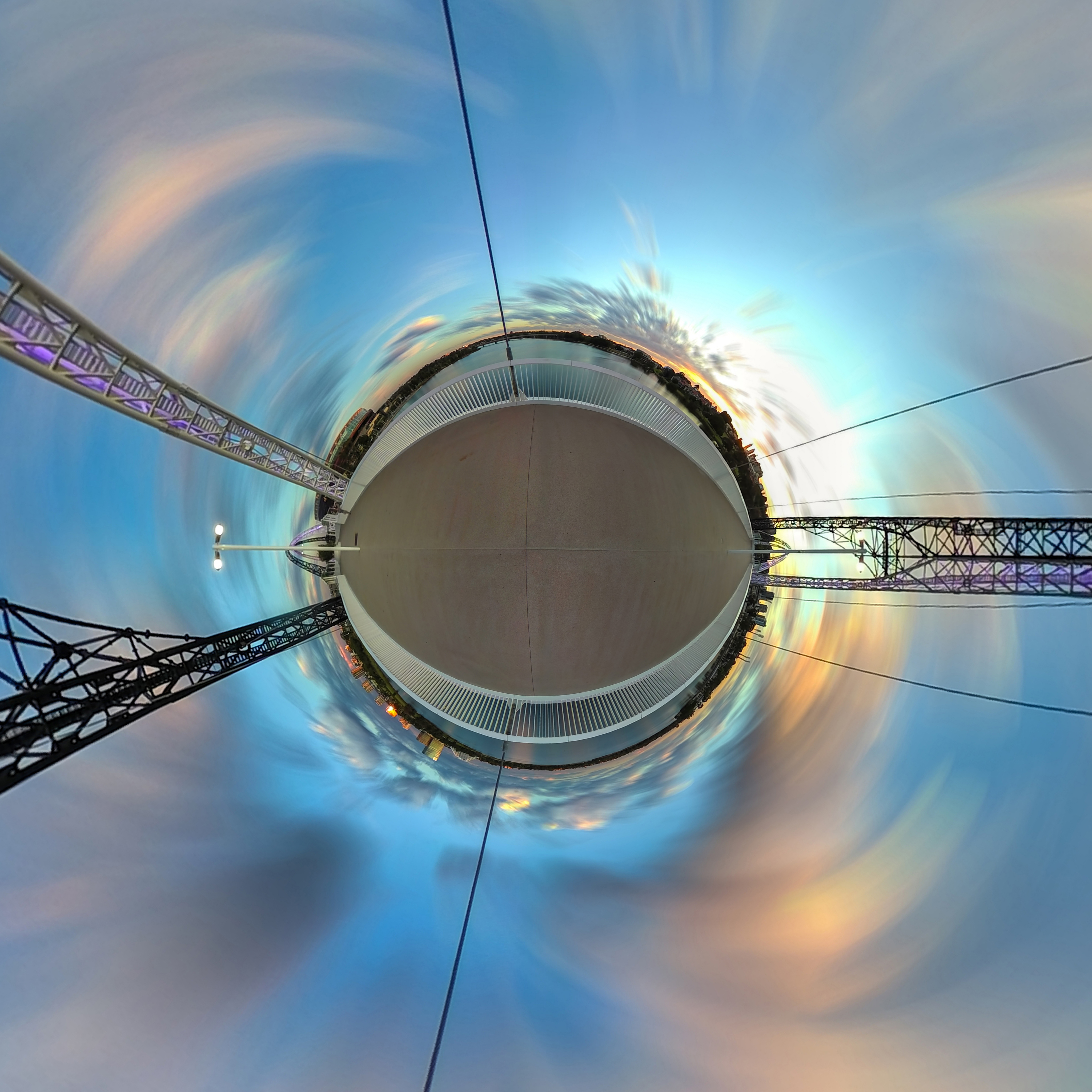
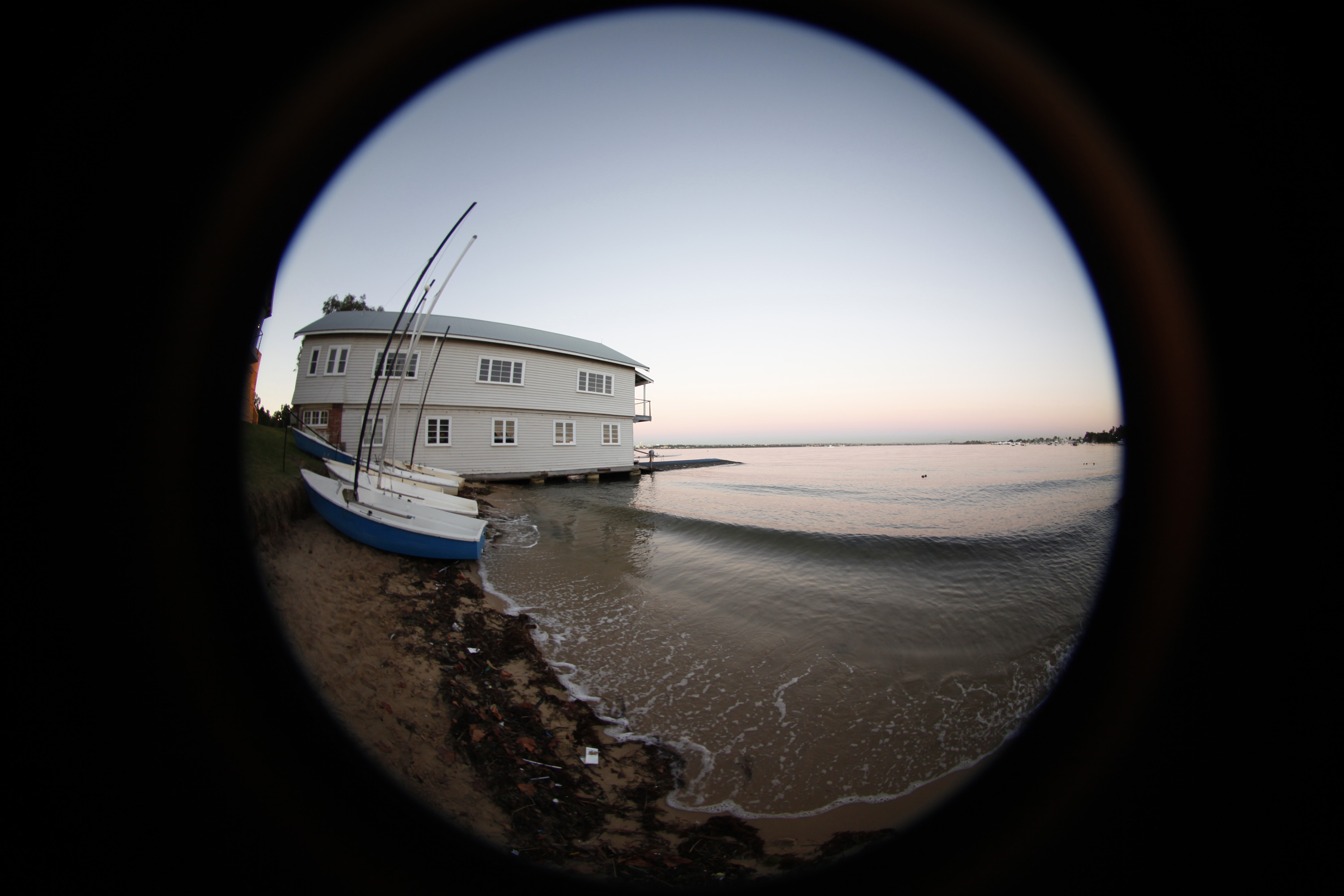
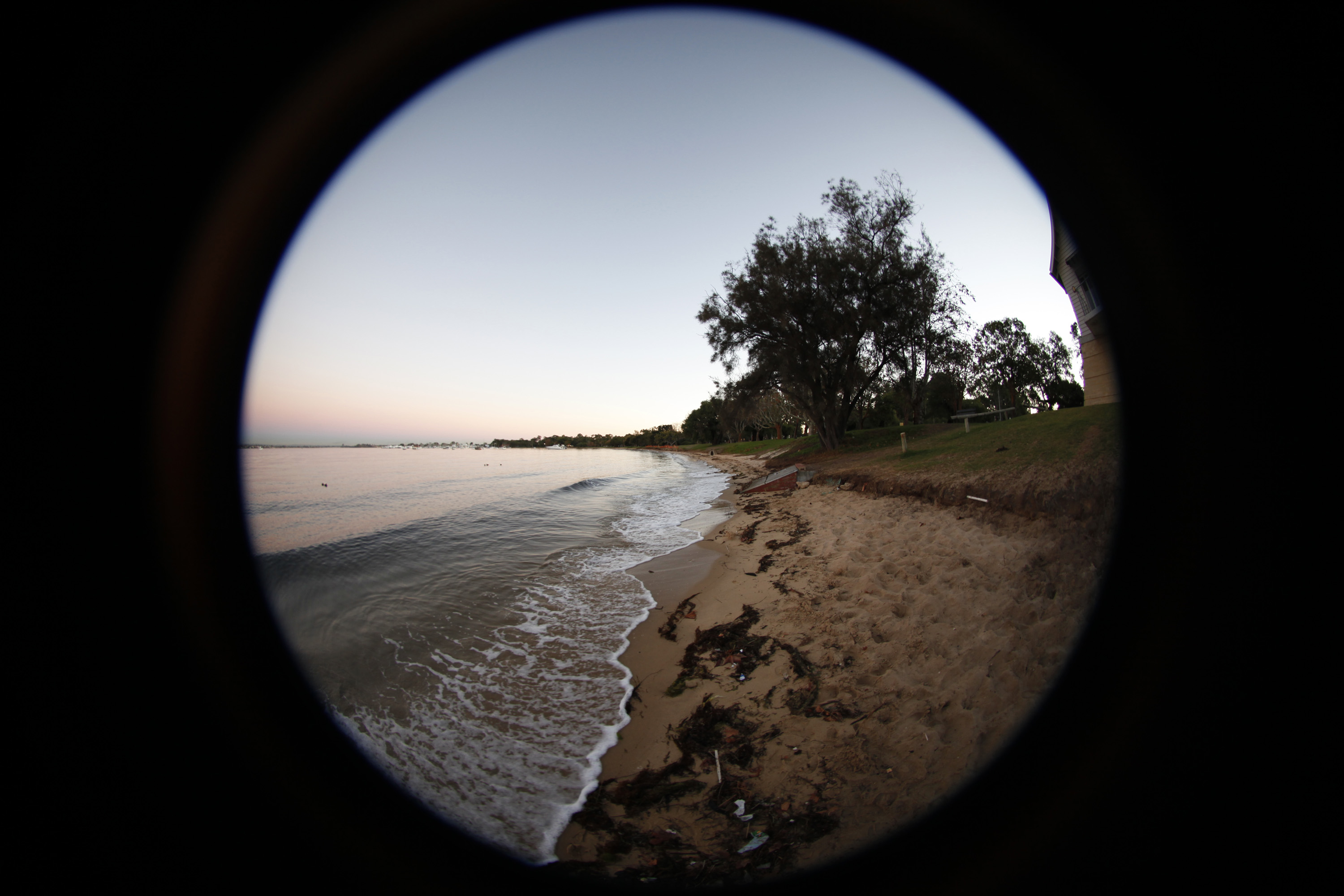
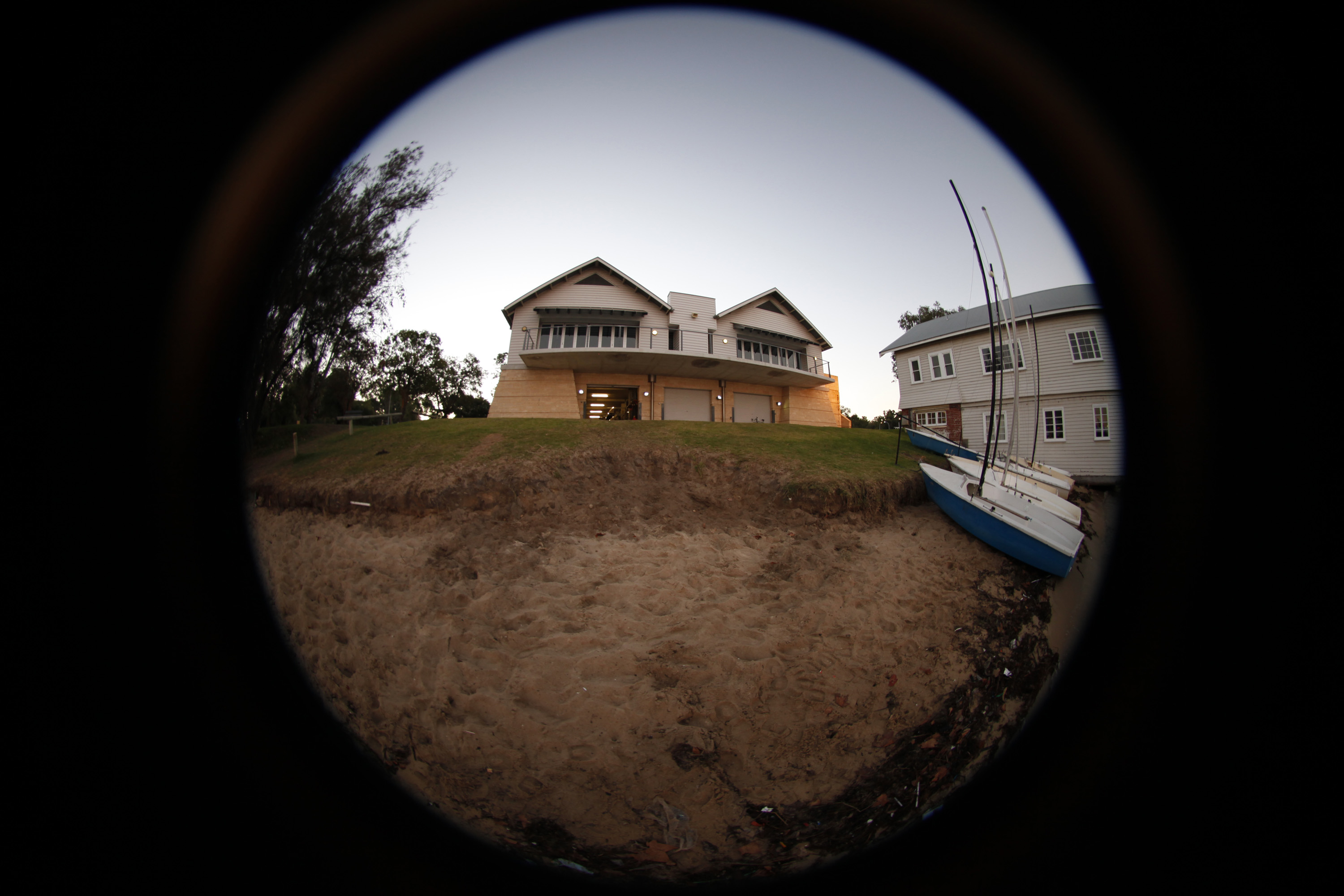
The images here are created using stereographic projections, it is one of the many ways of mapping points on a sphere onto a plane. Since a sphere and a plane are topologically different forms, the mapping cannot be performed without some form of distortion. Stereographic projections, also called planisphere projections have been employed by Hipparchus and documented by Ptolemy, it arises as a way of mapping spherical data onto an image plane in a range of fields that include astronomy, cartography, geology, and mathematics. The first stage is the creation of a spherical projection, otherwise known as a equirectangular projection of a sphere. There are many ways of doing this photographically, they are mostly distinguished from each other by the final image resolution. The simplest is with a 180 degree fisheye lens and SLR camera. Three images are captured each separated by 120 degrees horizontally.
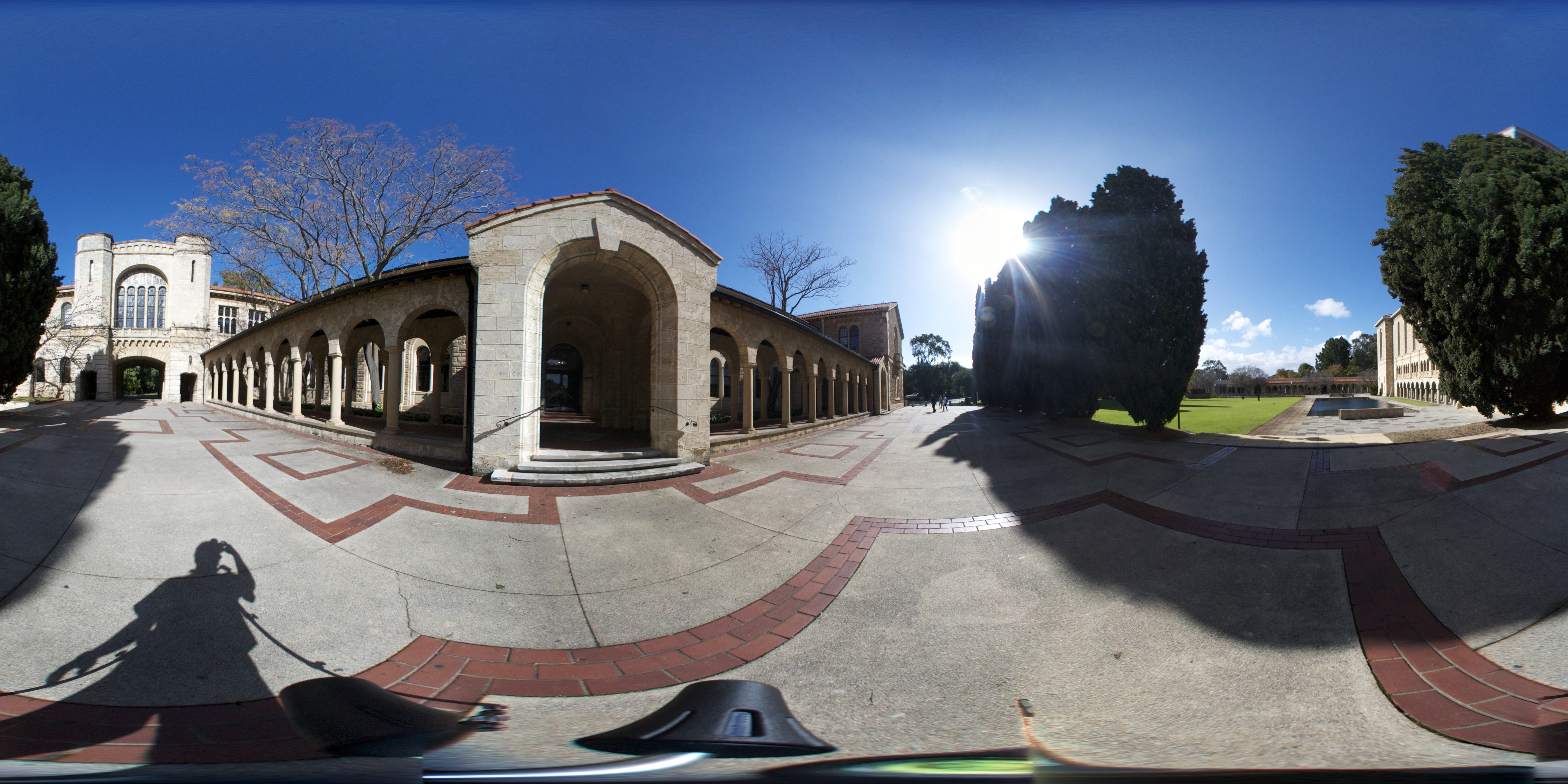
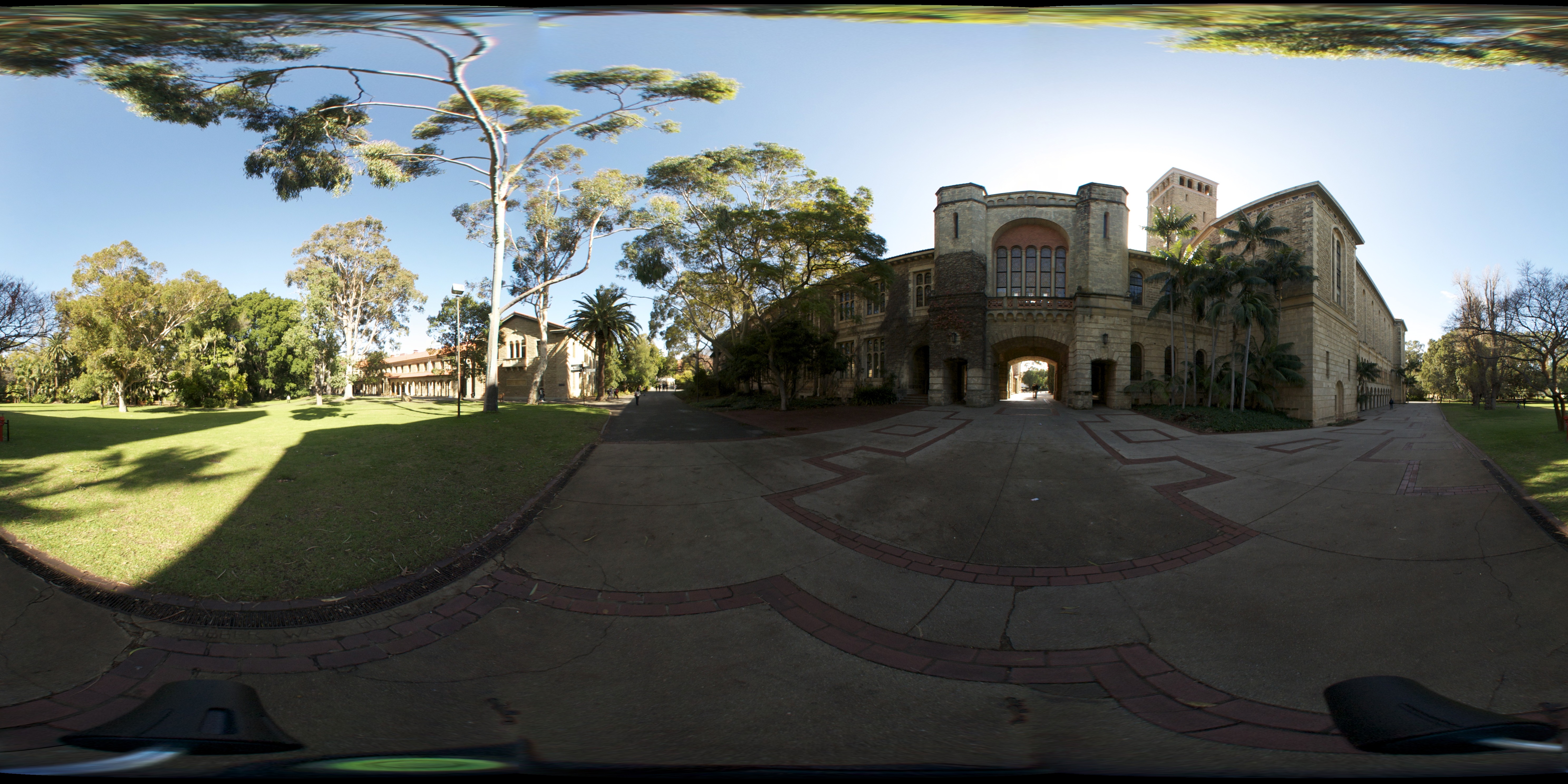
Since these three images capture the entire visual field, 360 degrees horizontally and 180 degrees vertically, they can be stitched and blended together to form a spherical projection, as follows. 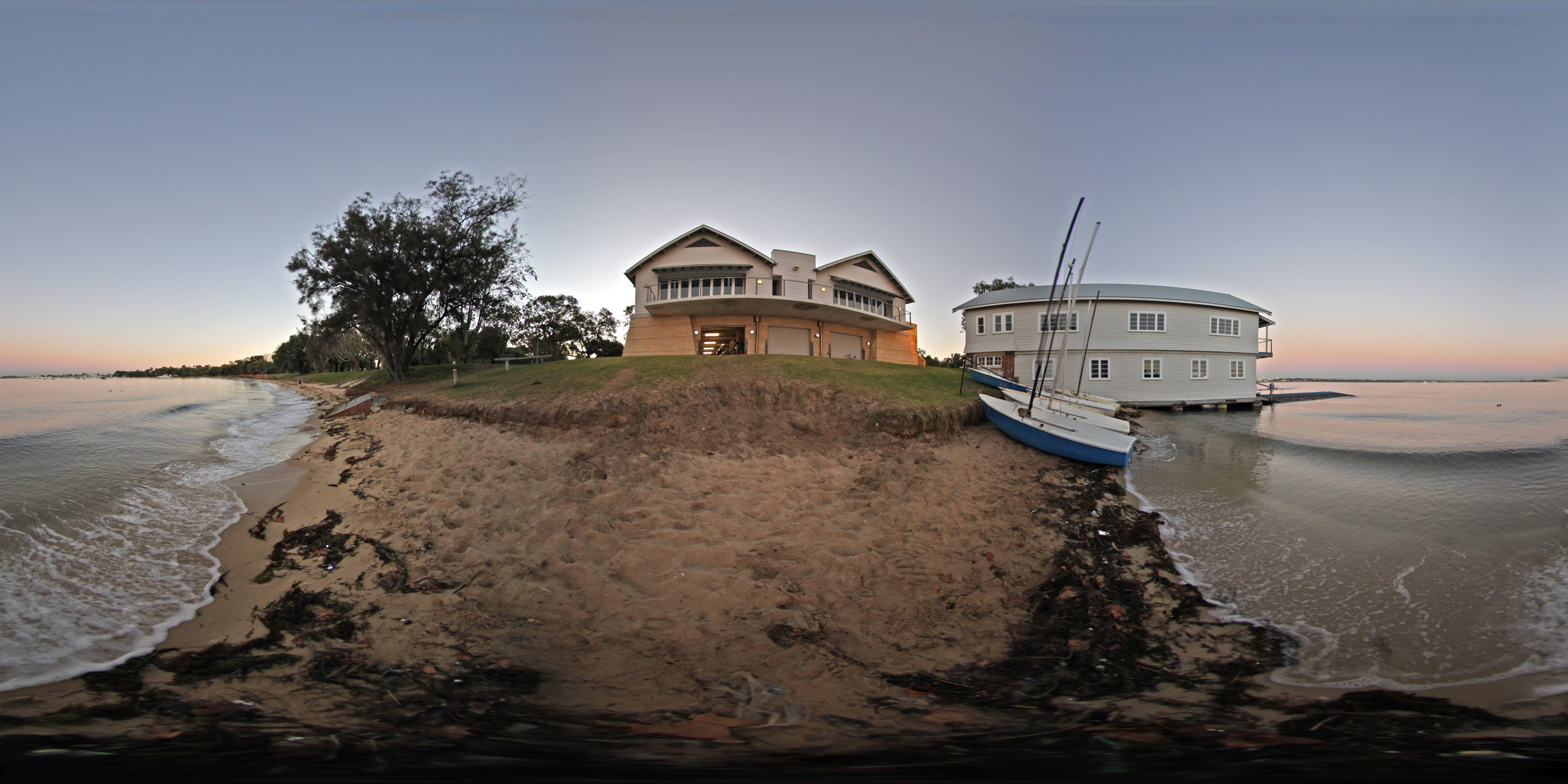
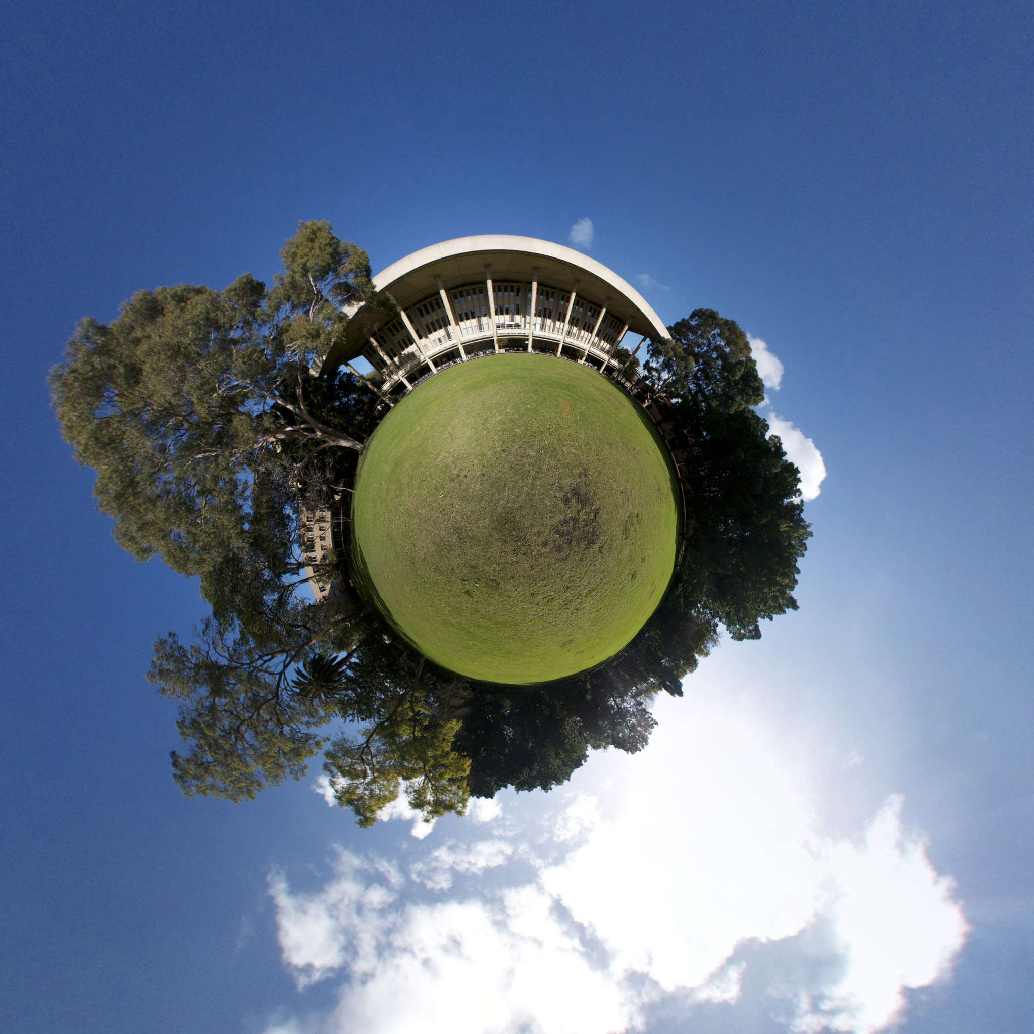
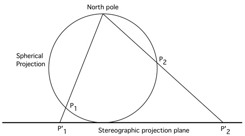
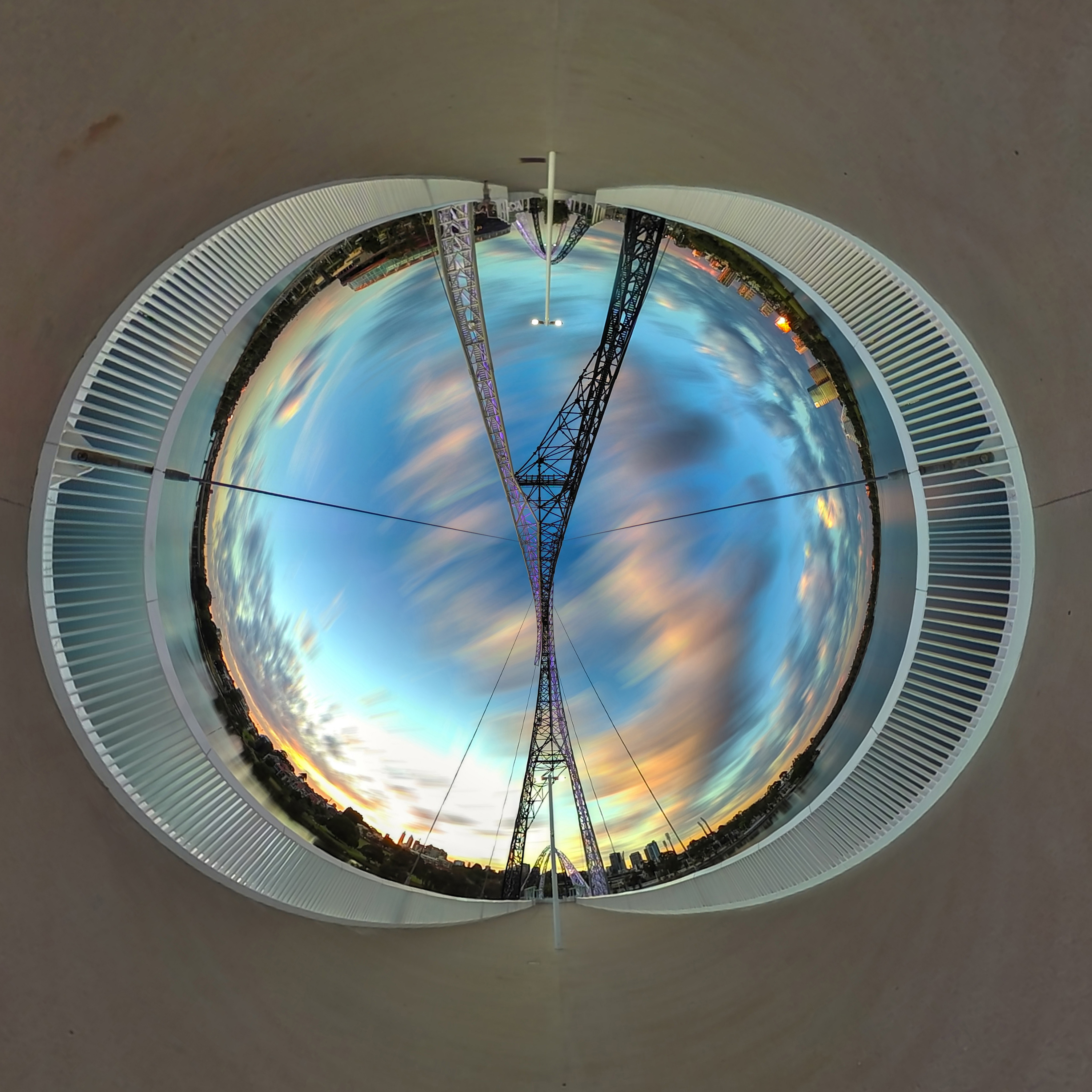
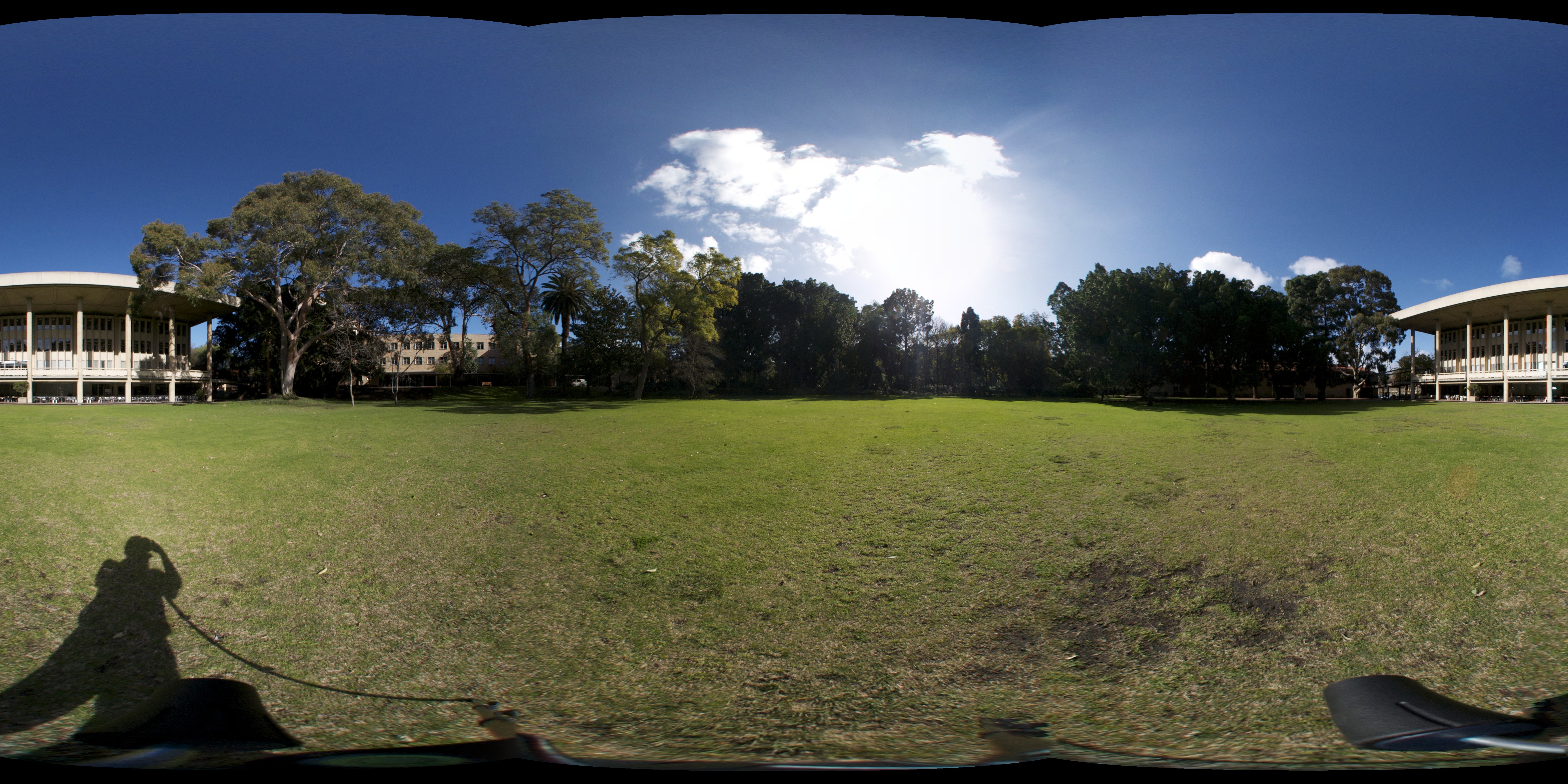
It is this image, mapped as a texture onto a sphere, that can be projected onto a plane using a stereographic projection. A stereographic projection involves selecting a focal point (normally along a vertical line through the origin) and a plane which will become the projected image plane. To determine where any point on the sphere maps to on the image plane, a ray is drawn from the focal point through the point in question. Where this ray intersects the image plane is the projected position. In this case the focal point is the north pole of the sphere and the image plane is tangential to the sphere and touches the south pole. This is illustrated below for two points in the image, the top of the building roof and the yacht mast. 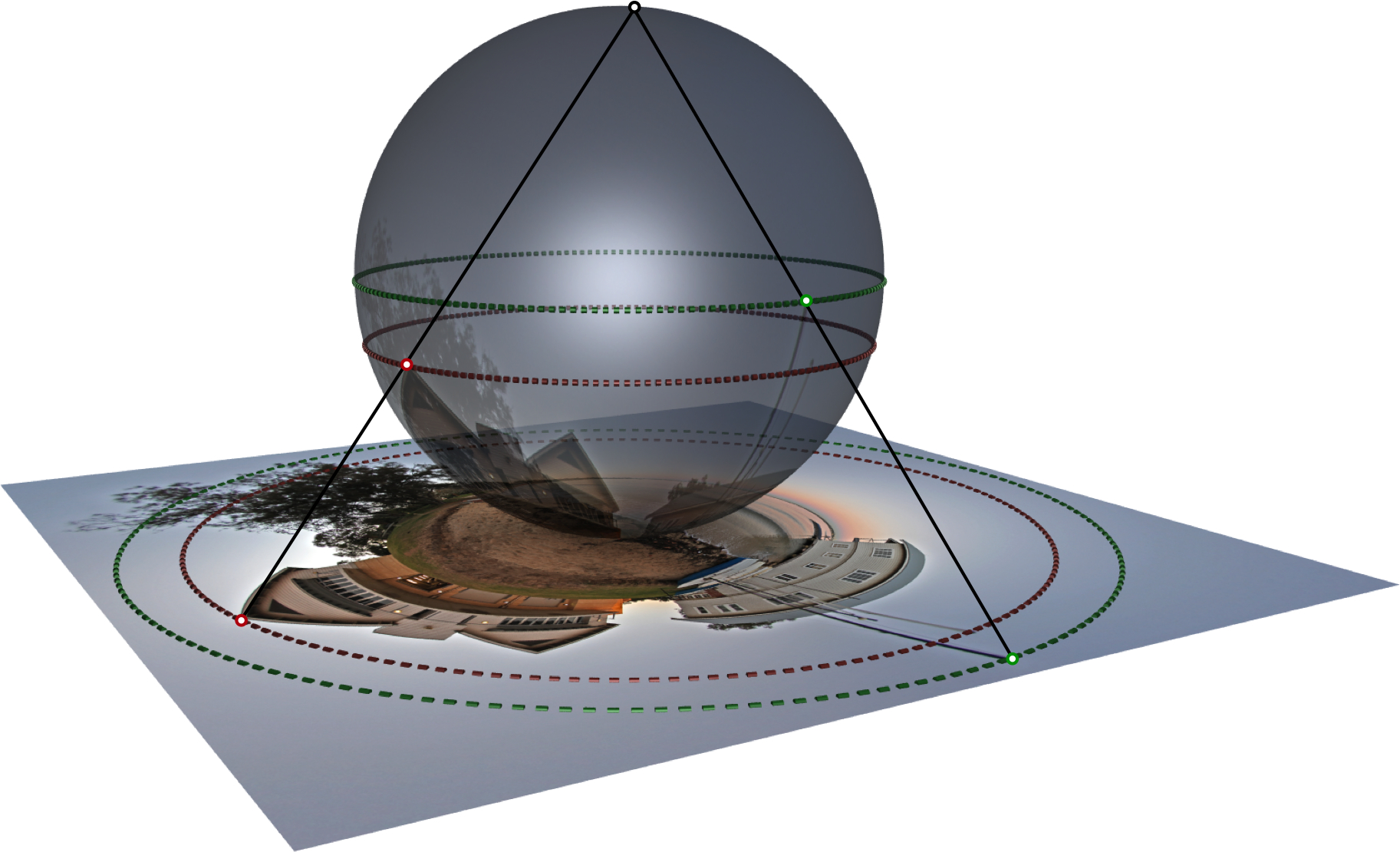
Stereographic projections preserve angles (conformal) but they do not preserve lengths (obvious if one considers what happens to points towards the north pole) and it therefore follows that it does not preserve area (isometric). The projection is smooth (no discontinuities), at least for points on the sphere between the focal point and the image plane.
Extreme Fisheye Projections
Written by Paul Bourke |