Title: Canon RF 5.2mm f/2.8L Dual Fisheye lensAlternative title: The VR180 fallacyWritten by Paul BourkeDecember 2021 Update: July 2025. Canon RF-S3.9mm F3.5 STM Dual Fisheye Lens.
The following discusses an initial evaluation of the new (at the time of writing) pair of fisheye lenses, the "Canon RF 5.2mm f/2.8L Dual Fisheye" mounted on the Canon EOS R5. The target for this lens is predominantly the so called "VR180" market, that is, a stereoscopic viewing environment that fills our entire peripheral vision. The main desirable features of this photographic solution over many others are:
Of course, like everything in optics, photography and video, there have been similar splitting mirror designs in the past. The main difference here is the introduction of fisheye lenses.  Stitz SA-1, Made by Itzuki (Japan), circa 1970
First observation, the fisheyes are not centered. An easy fix and a common trait of all dual fisheye 360 cameras. But given the price point of this lens and camera surely the two fisheyes could be factory aligned. It means of course that one needs to correct the horizontal offset to align the image pairs and the vertical offset to remove any vertical parallax. It also means that every camera will be slightly different, requiring a different fisheye circle center and radius value. The fisheye circle is about 4010 pixels, rated as 190 degrees at that circle. Interocular is 6cm. The image below illustrates the vertical offset as well as the manual method for determining the fisheye centers and radii. 
The lens does have a higher light fall off towards the rim than most other similar fisheye lenses, and still exhibits some fall-off at the 180 degree mark. The following are two 180 degree fisheyes extracted after determining the horizontal position, correcting for the vertical offset and flipping the left and right half of the frame. These are now perfectly centered in each half of the frame. 
It will be left up to the reader to work out why the left eye image appears on the right hand side of the image. This is obviously so since the left and image should "see" the bulging fisheye lens from the right hand camera. So after processing the two bulging lenses should appear in the center of the combined frame. The next correction that needs to occur is linearising the fisheye, that is, a radial correction such that the field angle is a linear function of distance from the fisheye center. This is discussed here in more detail. It is a shame that Canon does not publish this information and even finds it necessary to refuse requests for it, unlike most other fisheye lens producers. This is as much a key attribute of the lens as the field of view or f number. Indeed, this curve is necessary for anyone who wishes to use the images correctly in almost any VR environment. Almost any downstream usage of the footage is going to assume a linear relationship, not doing this will result in errors in perceived scale in, for example, VR headsets. It is possible to measure it oneself and the results are given below but Canons attitude with respect to such basic information is unforgivable. As it happens this lens is extremely linear. The graph below is normalised radius vs field angle. Field angle phi = r / (0.5*190*pi/180) = 0.6031 r where r is normalised radius of the fisheye circle. For the vast majority of applications no further correction would be required. 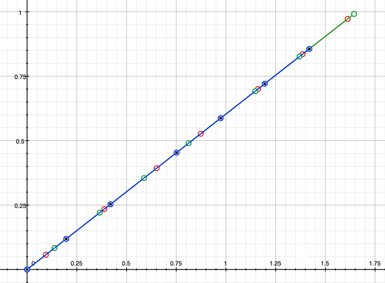
Unlike many of the comments from Canon, it is not necessary to use their paid tools to edit this footage. Whether the pipeline uses fisheye (see extracted image pairs above) or pair of 180 degree longitude equirectangulars shown below, there are lots of conversions options. 
The alternative and more traditional approach to stereoscopic video is to use two discrete cameras. Since the physical size of many cameras is greater than 6.5cm (average human interocular) then it's common practice to use a beam splitter (half silvered mirror) approach. Unfortunately this solution is not possible for fisheye optics. While there are small enough video cameras it is rare for them to support genlock, some claim to do so but often in reality they only support synchronised start. These solutions generally incur drift over time, and synchronised start is usually only as good as 1/2 the frame rate. By comparison, using a single sensor ensures perfect synchronisation between the two eyes.  180 stereoscopic video in a LED based cylinder
 180 stereoscopic video in a 4m diameter hemispherical dome The VR 180 fallacy
There is a fallacy in much of the marketing of this lens, typical are statements like the following that appear multiple times on the Canon web site, and regurgitated by reviewers. or
In reality the view one experiences is only strictly correct if one is looking directly forward. Only in this situation are the two fisheye views presenting a reasonable model of the the human visual system. There are two obvious situations to illustrate why the above statements are not true, or at best misleading.
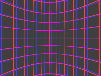
The effects described above are not due to imperfect fisheye optics in a physical lens but are fundamental to any single shot dual fisheye camera. For example, one can recreate the perfect case with computer graphics, the following is a simulation of the two Canon RF 5.2mm f/2.8L dual fisheye lenses but with perfect optics (190 degrees FOV). The scene is a simple latitude/longitude grid a fixed distance from the center between the two lenses. The two fisheye images have been overlaid, the left eye in blue and the right eye in red. 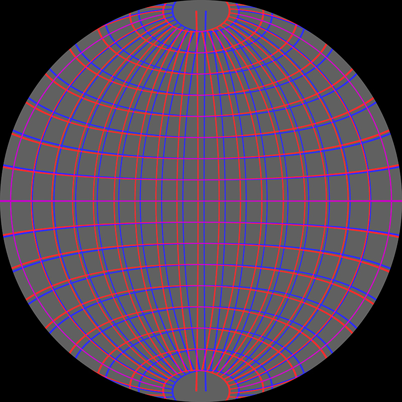
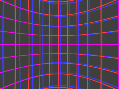
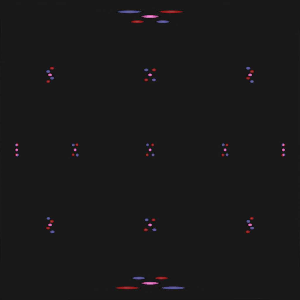
All the effects discussed can be observed in this image. Noting that the lenses are parallel as expected for VR headset style viewing, so zero parallax is at infinity and the relative location of scene elements should exhibit negative parallax. In other words the blue lines (left eye) should always be to the right of the red lines (right eye). Along the horizontal axis this separation decreases towards the edges, in the extreme case there is no depth perception. The vertical parallax is clear along the four diagonals, and in different directions depending on the quadrant being considered. Again, note that these effects are the correct behaviour for a forward looking observer, but they make the statements above about being able to turn ones head, incorrect, at least for correct stereoscopic viewing. Turning ones head away from the central direction will result in incorrect depth perception and increased eye strain as the human visual system is presented with "unexpected" stereoscopic pairs and tries to compensate. These effects do not "go away" when converting to equirectangular, the issues just get revealed in different parts of the image. The following is the equirectangular corresponding to the simulated image above, this is also 190 degrees FOV. 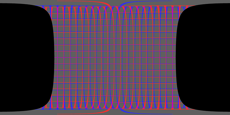
These stereo pairs can also be viewed, in pieces, by perspective views. In the following each perspective camera is 100 degrees horizontal field of view, the adverse effects discussed above are visible in this representation also.
Screen based stereo and the convergence problem
In order to understand the effects of projecting onto a screen based stereoscopic system, for example, the iDome display, a simulation of the Canon and fisheye lenses will be used along with some simple scene elements. The coordinate system and geometry is as shown, the L and R are the location of the fisheye lenses and three small spheres will be placed at the distances as shown. These three spheres will also be rotated by +/-45 degrees and +/-80 degrees so as to lie along the horizontal plane, +/-45 and +/-80 degrees so as to lie along the vertical axis. A further 4 instances of the 3 spheres will be positioned so as to be located in each quadrant. Because only rotations are used, the distances indicated are preserved for all spheres. 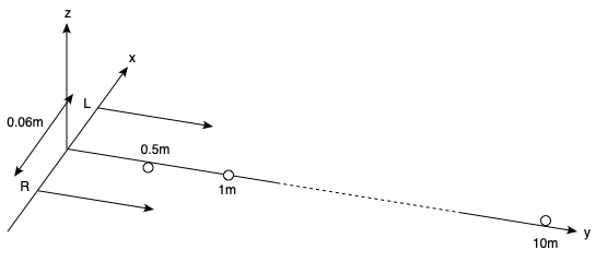
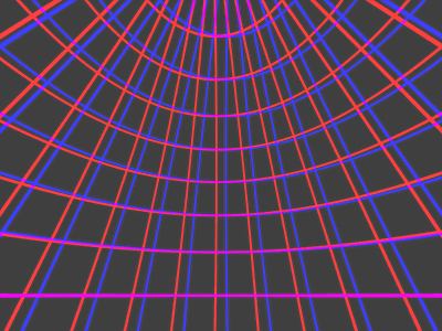
As earlier, the resulting images will be overlaid with the spheres in the left eye image being blue and the spheres in the right eye image being red. The fisheye rendering using a 190 degree ideal fisheye is as follows. 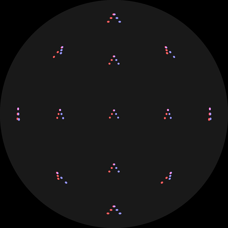
Most effects have already observed with the latitude/longitude grid earlier.
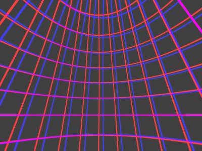
While it may seen risky to make observations from the fisheye images, one can readily extract perspective views. This will be left as an exercise for the reader, but while the appearance of the features changes, the conclusions are the same. The 180 degree longitude equirectangular representation of the above is shown below. 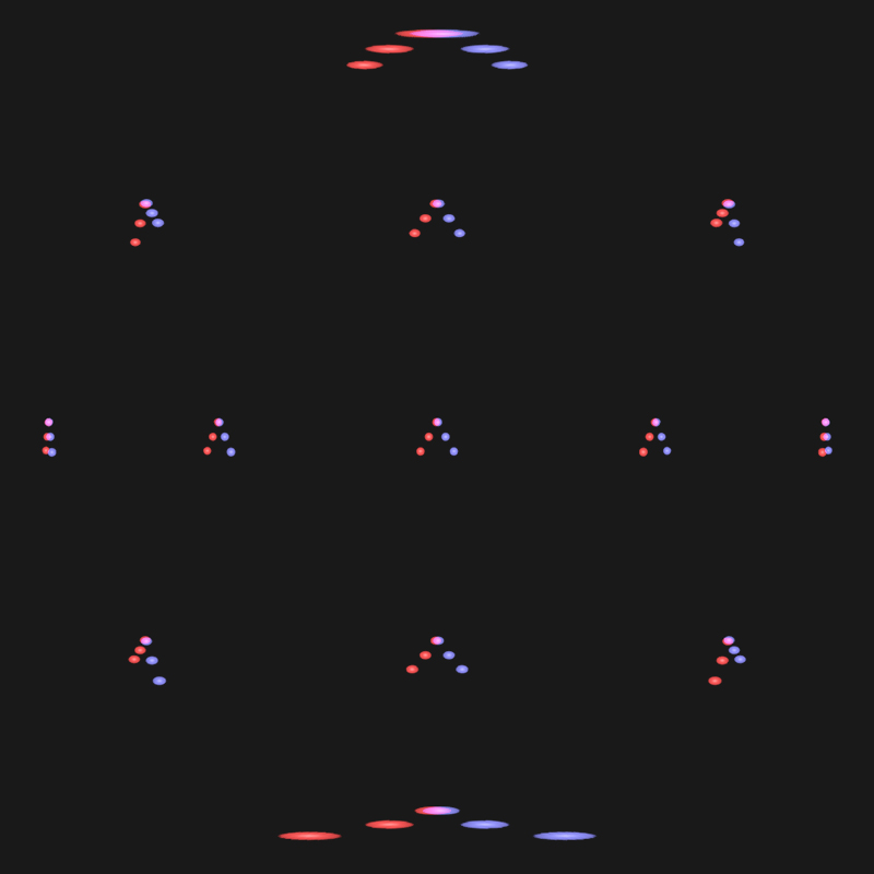
For screen based stereoscopic systems one needs to choose a zero parallax distance, this is the distance at which scene objects will appear to be at the screen depth. For dimensional correctness (if that is required) the zero parallax distance as determined by the distance of the viewer to the display surface would match the distance of objects in the recorded scene. For flat wall stereoscopic displays the matching of zero parallax distance can be made exactly, this is performed by horizontally sliding the left and right images with respect to each other and trimming off the excesses. This process mimics the asymmetric frustum used in real-time computer graphics head tracking systems. Essentially matching the view frustum of the camera with the projection pyramid from the projector. One way to align an object at a known distance from the camera to lie on the screen surface is to rotate the fisheye image about the vertical axis. For the simulated test scene described above the angle to rotate the fisheye image by in order to set the zero parallax point can be exactly calculated. The result is shown below for both overlaid fisheyes and overlaid partial equirectangulars after the image has been rotated to place the 1m sphere at the screen depth. 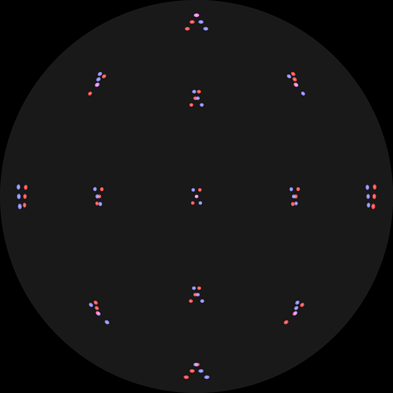
Observations.
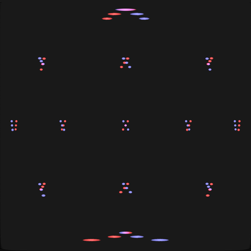
This is similar to rotating the cameras in perspective based stereo such that the optical axis of the cameras converge at a point, otherwise known as toe-in stereoscopic generation. It is strongly discouraged in perspective style stereoscopy and it would appear to be equally undesirable here. Another alternative is to create a so called "offaxis fisheye" transformation in order to align objects at a known depth to the screen depth. Again, the degree of offset can be computed exactly for this test case, in order to place the 1m distant object at zero parallax. As before, the result is shown below as an overlaid fisheye and as an overlaid equirectangular. 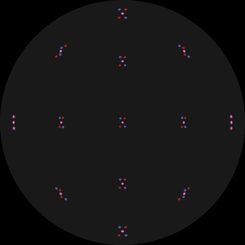
Observations.
The general conclusion is the same, specifically, that while 180 degree stereoscopic captured with dual parallel fisheye lenses can give acceptable viewing, it is only strictly correct for a viewer looking "forward". Note that there being two ways one can turn ones head to view along the diagonals. One method is that one imagines the head panning left-right and then tilting up-down with the eyes staying horizontal. The second model is to imagine the head rotating in arcs, in which case the eyes do not stay level. Unfortunately neither of these solves the issue, and the later which might expect a vertical parallax solution doesn't because the vertical parallax introduced is in the wrong direction. There is another model for head movement where the eyes do tilt in the angle of the introduced vertical parallax, but it's a fairly unnatural viewing model. There are alternatives, these are generally known as omnidirectional stereoscopic methods and they exist for both 360 cylindrical displays as well as hemispherical dome displays. They allow a viewer to look left and right and the stereoscopic depth perception remains correct along a horizontal view direction, the price is incorrect depth perception in the periphery but that is widely accepted as less important. Unfortunately (at the time of writing) there are no "perfect" omnidirectional cameras for video, but they do exist for still images. So called 3D 360 video cameras create approximations to the omnidirectional stereoscopic ideal but still exhibit depth perception errors as well as the inevitable issues across stitching zones. Addendum 1
Why is the left eye image located on the right hand side? This is one of the first things one notices, for example, the image on the left of the frame has the view of the other lens located on the left of its frame, so it must be the right eye. 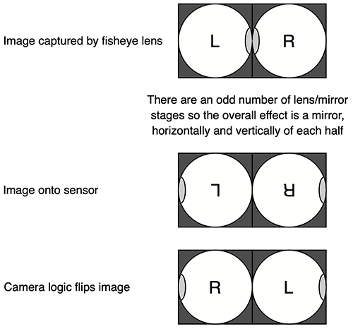
Perhaps the real question is why doesn't Canon simply flip each of the halves of the frame as part of it's image processing pipeline? The firmware knows when this lens is attached. Addendum 2: Canon RF-S3.9mm F3.5 STM Dual Fisheye Lens
This more recently released dual lens from Canon is intended for their APS-C sensor line of cameras. Unfortunately with regard to immersion, the fisheye lenses are only around 150 degrees field of view. So it's more of a wide angle stereoscopic camera than a "VR" camera. Note that the Canon specifications quotes 144 degrees FOV, but the authors estimate is closer to 155 degrees, a strange discrepancy. As with the "Canon RF 5.2mm f/2.8L Dual Fisheye lens" this lens also has a 60mm interocular. 
The fisheye circle arrangement on the Canon R7 (6960x4640) looks like the following, the center of the fisheye circles will vary in position and radius with the manufacturing variations. The fisheye circle is 3200 pixels diameter. 
As usual there are some strange aspects to the Canon description for this this lens. In particular "Another advantage is being able to use a tripod, gimbals or microphones and not having them end up in the shot." At the end of the day if one is careless enough to leave gimbals, tripods or microphones in the shot with, for example, the Canon RF 5.2mm f/2.8L Dual Fisheye lens, then it's a simple crop to a smaller FOV to remove them. The following illustrates what the field of view on this lens is within a side-by-side half equirectangular frame. 
Povray implementation using "user_defined" camera
The following implements the mathematics for the above lens as a "user_defined" camera in Povray. This special, but extremely versatile, camera requires one to define the source position and direction vector of the ray for every position on the image (fisheye) plane. The comments above apply here, specifically, the stereoscopy is only strictly correct for a viewer looking directly forward. Both zero parallax at infinity (for head mounted displays) and zero parallax at a fixed distance for screen based displays is supported.
#version 3.8;

/*
   Experiment with stereo fisheye using PovRay user_defined camera in version 3.8
	This is not ODSP, but two cameras with zero parallax controls
   Designed for a vertical iDome.
   Deals with left and right eye separately, suggest ffmpeg to create left/right arrangement
   Handles positioning of zero parallax, typically at screen distance or infinity
   Assumes right handed coordinate system
	"z" is up, "x" is to the left or right, "y" is forward.
   The camera rig can be panned in order to set where "front" (y axis) corresponds
   All length units in meters
*/

#declare DOMERADIUS = 1.5;

#declare FISH_camerax = 0;                                   // View position
#declare FISH_cameray = 0;
#declare FISH_cameraz = 0;

#declare FISH_eyesep = 0.065/2;                              // Half the eye separation
#declare FISH_whicheye = -1;                                 // -1 for left, 1 for right, 0 for center
#declare FISH_parallax = DOMERADIUS;                         // Distance to zero parallax
                                                             // Set to very large number for infinity
#declare FISH_parangle = atan(FISH_eyesep / FISH_parallax);  // Rotation angle to set zero parallax
#declare FISH_panangle = radians(0);                         // Pan the camera rig
                                                             // Mostly to control where "front" is on the panorama
#debug concat("FISH_parangle: ",str(degrees(FISH_parangle),5,2),"\n")

// Fisheye
camera {
   user_defined
   location {
      function { FISH_camerax + FISH_whicheye * FISH_eyesep * cos(FISH_panangle) }
      function { FISH_cameray + FISH_whicheye * FISH_eyesep * sin(FISH_panangle) }
      function { FISH_cameraz }
   }
   direction {
      function { sin(pi*sqrt(x*x+y*y)) * cos(atan2(y,x)) * cos(FISH_panangle - FISH_whicheye*FISH_parangle) +
         cos(pi*sqrt(x*x+y*y)) * sin(FISH_panangle - FISH_whicheye*FISH_parangle) }
      function { cos(pi*sqrt(x*x+y*y)) * cos(FISH_panangle - FISH_whicheye*FISH_parangle) -
         sin(pi*sqrt(x*x+y*y)) * cos(atan2(y,x)) * sin(FISH_panangle - FISH_whicheye*FISH_parangle) }
      function { sin(pi*sqrt(x*x+y*y)) * sin(atan2(y,x)) }
   }
}

|