Additional cameras, mostly stereoscopic, for PovRay
Perspective stereoscopic -
Stereoscopic cylindrical panorama
Alternative title: Example of creating a special camera for PovRay |
 |
 |
Alternatively by overlaying the images with a 50% transparency one should be able to verify the correct stereoscopic relationships, for example, the correct positive and negative parallax for each component.
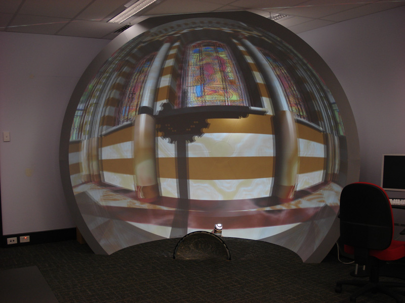
A stereoscopic panoramic image is a very precise projection intended for full or partial
cylindrical projection environments, such as the AVIE.
They have the benefit over most surround stereoscopic
displays in that the viewer may look in any direction and the stereoscopic effect is achieved
without any head tracking. To a close approximation it also means that multiple people can
inhabit a full 360 degree stereoscopic display, each looking in a different direction,
something that is not possible with standard flat wall surround stereoscopic displays.
For more information see this page.
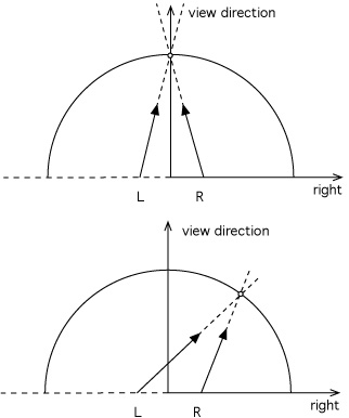
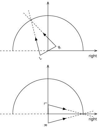
There are two ways of creating a stereoscopic panoramic pair, they are almost (but not quite)
identical. The difference is a slightly different camera separation ... a difference that
becomes smaller as the ratio of the zero parallax to eye separation becomes large.
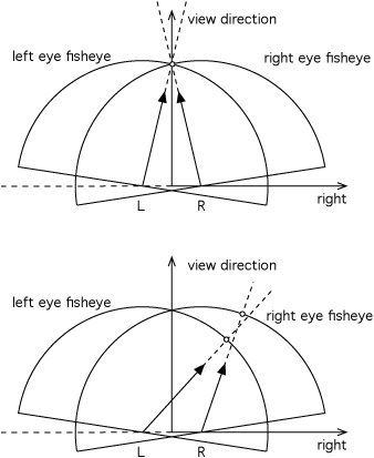
Using parallel cameras results in zero parallax
at infinity, a particular parallax can be achieved by circularly translating the panoramic
images horizontally. The second is to encode a particular zero parallax distance into the
panoramic at render time by using the so called "toe-in" cameras. While this is incorrect
for perspective projections it is identical to the parallel camera case but with a different
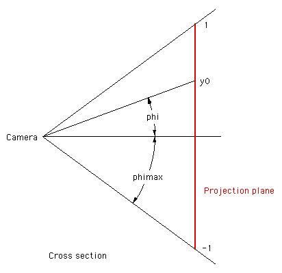
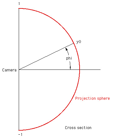
effective eye separation. The expression can be derived from the diagram on the right, namely:
The conventions for using this camera are similar to those for the perspective stereoscopic
camera defined above. There are the same two new keywords "zero parallax" which indicates
the distance to zero parallax (could be very large if infinity is required), and "eyeoffset"
which is half the eye separation. Typically the scene would be rendered twice, once for the
left eye (negative eyeoffset) and once for the right eye (positive eyeoffset).
Since this is a very precise camera type, many of the other camera parameters are not
used. In particular, only square pixels are supported and the magnitude of the right vector
is ignored. Also, the vertical field of view is derived from the image width and height
(assuming square pixels). The vertical field of view phimax is given by:
Most of the comments for the stereoscopic perspective discussion also apply here
so won't be repeated.
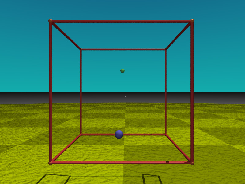
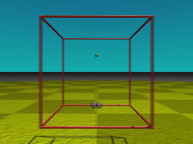
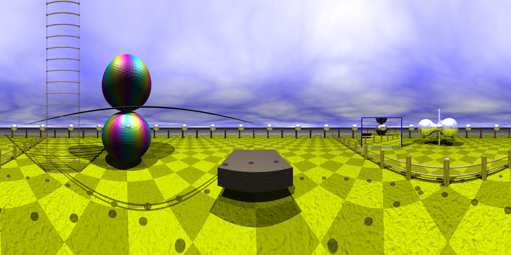
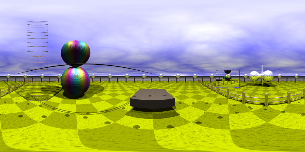
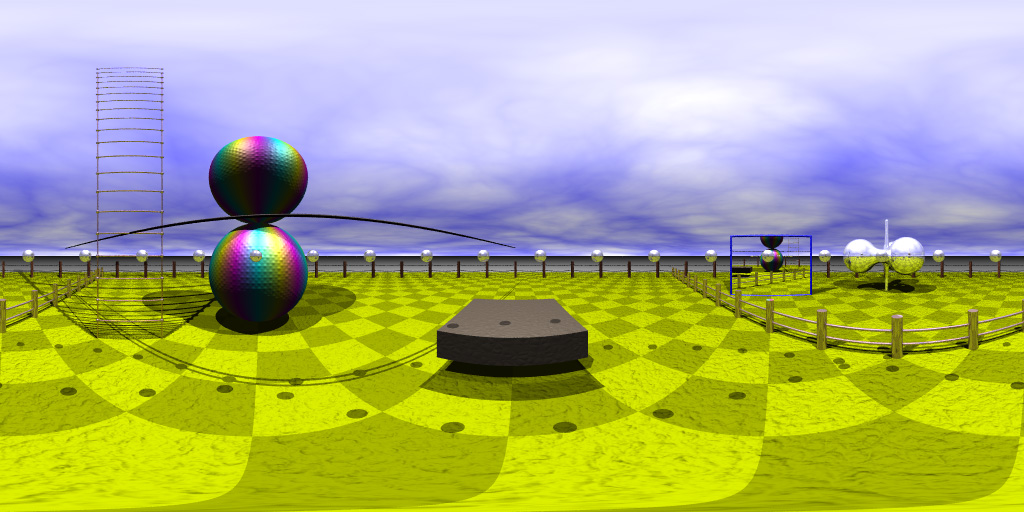
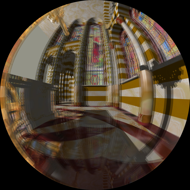
As for the stereoscopic perspective case, another very precise scene is designed
that results in the following images.
The small spheres around the middle of the image should appear exactly at zero parallax.
When viewed correctly the spheres should all appear round.
Stereoscopic cylindrical panorama
#declare VP = <0,0,2>;
#declare EYESEP = 0.1;
#declare ZEROP = 2.0;
camera {
   stereopanorama
   location VP
   up y
   // The length of the this right vector is actually ignored
   right -x
   angle 360
   sky <0,0,1>
   look_at VP + <0,1,0>
   // Distance to zero parallax
   zeroparallax ZEROP
   // Use -'ve for left eye and +'ve fpr the right eye
   eyeoffset -0.5*EYESEP + clock*EYESEP
}
    /*
     * pdb - Stereoscopic panoramic camera
     * Assume 360 degrees longitude
     * The vertical FOV (for square pixels) is derived from the ratio of the image width and height
     */
    case STEREOPANORAMA_CAMERA:

      // Normalise projection plane coordinates
      x0 = x / (DBL)Frame.Screen_Width; // 0 .. 1
      y0 = 2.0 * ((DBL)(Frame.Screen_Height - 1) - y) / (DBL)Frame.Screen_Height - 1.0; // -1 ..1

      // Angle to align zero parallax
      dtheta = atan(Frame.Camera->Eye_Offset / Frame.Camera->Zero_Parallax);

      // Get polar coordinates for ray
      theta = x0 * TWO_M_PI;
      phi = atan(y0 * Frame.Screen_Height * M_PI / Frame.Screen_Width);

      // My own unit vector versions
      VNormalize(vd,Frame.Camera->Direction);
      VNormalize(vr,Frame.Camera->Right);
      VNormalize(vu,Frame.Camera->Up);

      // Primary ray source
      VLinComb3(Ray->Initial,Frame.Camera->Eye_Offset*cos(theta),vr,0.0,vu,-Frame.Camera->Eye_Offset*sin(theta), vd);
      Ray->Initial[0] += Frame.Camera->Location[0];
      Ray->Initial[1] += Frame.Camera->Location[1];
      Ray->Initial[2] += Frame.Camera->Location[2];

      // Create primary ray direction
      theta -= dtheta;
      VLinComb3(Ray->Direction, sin(theta), vr, tan(phi), vu, cos(theta), vd);

      initialize_ray_container_state(Ray, true);
      break;
Stereoscopic spherical projection
#declare VP = <0,0,2>;
#declare EYESEP = 0.1;
#declare ZEROP = 2.0;
camera {
   stereospherical
   location VP
   up y
   // The length of the this right vector is ignored
   // The image width should equal twice the image height
   right -x
   // Only 360 x 180 (full) spherical projection supported
   angle 360
   sky <0,0,1>
   look_at VP + <0,1,0>
   // Distance to zero parallax
   zeroparallax ZEROP
   // Use -'ve for left eye and +'ve fpr the right eye
   eyeoffset -0.5*EYESEP + clock*EYESEP
}
When viewed correctly the spheres should all appear round. The small spheres along the horizon should be at zero parallax.
 |
 |
    /*
     * pdb - Stereoscopic spherical camera
     * Assumes a full 360 by 180 spherical projection
     * imagewidth should equal 2 * imageheight for correct proportions
     */
    case STEREOSPHERICAL_CAMERA:

      // Normalise projection plane coordinates
      x0 = x / (DBL)Frame.Screen_Width; // 0 .. 1
      y0 = 2.0 * ((DBL)(Frame.Screen_Height - 1) - y) / (DBL)Frame.Screen_Height - 1.0; // -1 ..1

      // Angle to align zero parallax
      dtheta = atan(Frame.Camera->Eye_Offset / Frame.Camera->Zero_Parallax);

      // Get polar coordinates for ray
      theta = x0 * TWO_M_PI;
      phi = y0 * M_PI_2;

      // My own unit vector versions
      VNormalize(vd,Frame.Camera->Direction);
      VNormalize(vr,Frame.Camera->Right);
      VNormalize(vu,Frame.Camera->Up);

      // Primary ray source
      VLinComb3(Ray->Initial, Frame.Camera->Eye_Offset*cos(theta), vr, 0.0, vu, -Frame.Camera->Eye_Offset*sin(theta), vd);
      Ray->Initial[0] += Frame.Camera->Location[0];
      Ray->Initial[1] += Frame.Camera->Location[1];
      Ray->Initial[2] += Frame.Camera->Location[2];

      // Create primary ray direction
      vt1[0] = 0;
      vt1[1] = 0;
      vt1[2] = 1;
      VRotateX(vt2,vt1,phi);
      VRotateY(vt1,vt2,-theta+dtheta);
      VLinComb3(Ray->Direction, vt1[0], vr, vt1[1], vu, vt1[2], vd);

      initialize_ray_container_state(Ray, true);
      break;
Offset fisheye
There are two situations where a so called offset fisheye projection is required.
One arises when projecting using a fisheye lens on a data projector into a hemispherical
display and one wishes to place the projector at a location other than the center
of the hemisphere. This can simply be achieved with an image warping at projection
time and does not require a different rendering.
The other situation is when the viewer is not at the center of the dome, while this
can also be approximated by a image warping process, for strictly correct results
it requires a different rendering in order to capture the true parallax information.
#declare CAMHEIGHT = 2;
#declare VP = <0,0,CAMHEIGHT>;
camera {
   offsetfisheye
   location VP
   up y
   right -x
   angle 180
   sky <0,0,1>
   look_at VP + <0,1,0>

   // Offset, each should between -1 and 1
   fishxoffset 0.5
   fishyoffset 0
}
Example
 |
 |
 |
 |
 |
 |
Implementation
    /*
       pdb - Offset fisheye for planetariums with a shifted sweet spot.
       Essentially just translates the view vector in the plane of the hemisphere.
    */
    case OFFSETFISHEYE_CAMERA:

      // Normalised coodinates
      x0 = 2.0 * x / (DBL)Frame.Screen_Width - 1.0;
      y0 = 2.0 * ((DBL)(Frame.Screen_Height - 1) - y) / (DBL)Frame.Screen_Height - 1.0;

      // If the pixel lies outside the unit circle no ray is traced.
      if ((rad = sqrt(x0 * x0 + y0 * y0)) > 1.0)
        return(false);

      // Fisheye polar coordinates
      theta = atan2(y0,x0); // -pi .. pi
      phi = 0.5 * rad * Frame.Camera->Angle * M_PI_180;  // 0 .. aperture/2

      // My own unit vector versions
      VNormalize(vd,Frame.Camera->Direction);
      VNormalize(vr,Frame.Camera->Right);
      VNormalize(vu,Frame.Camera->Up);

      V1[0] = sin(phi)*cos(theta) - Frame.Camera->Fish_XOffset;
      V1[1] = sin(phi)*sin(theta) - Frame.Camera->Fish_YOffset;
      V1[2] = cos(phi);
      VLinComb3(Ray->Direction,V1[0],vr,V1[1],vu,V1[2],vd);

      initialize_ray_container_state(Ray, true);
      break;
Stereoscopic Fisheye
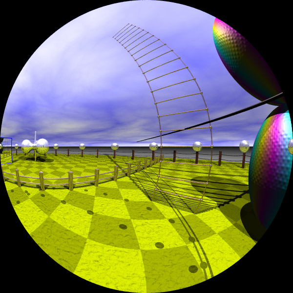
There are a number of ways one may imagine creating a stereoscopic fisheye pair. Perhaps the first idea would be take two normal fisheye projections and toe them in such that zero parallax is positioned correctly along the view direction.
 |
For example
#declare VP = <0,1,4.5>;
#declare VD = <1,0,0>;
#declare VU = <0,1,0>;
#declare VR = vnormalize(vcross(VD,VU));
#declare EYESEP = 0.07; // Human
#declare ZEROP = 1.5; // Dome radius
camera {
   fisheye
   location VP + 0.5*clock*EYESEP*VR
   up y
   right -x
   angle 180
   sky VU
   look_at VP + VD * ZEROP
}
|
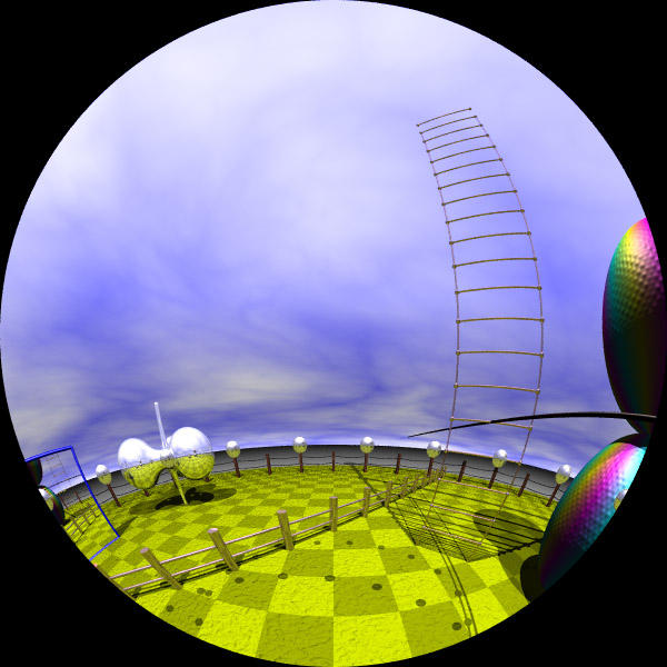
This leads to incorrect parallax estimation in a number of regions, particularly at the north and south pole, but there is also a mismatch at the edges.
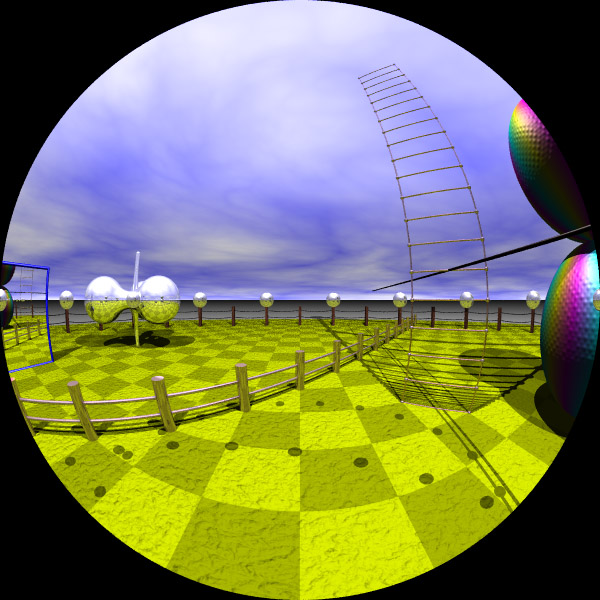
The next approach might be to imagine the eyes fixed and the fisheye projection surfaces coincident but the view vector is modified for each camera, similar to an offset fisheye. This is the first stereo fisheye projection implemented as a new camera "stereofisheye1".
 |
For example
#declare VP = <0,1,4.5>;
#declare VD = <1,0,0>;
#declare VU = <0,1,0>;
#declare VR = vnormalize(vcross(VD,VU));
#declare EYESEP = 0.07; // Human
#declare ZEROP = 1.5; // Dome radius
camera {
   stereofisheye1
   location VP
   up y
   right -x
   angle 180
   sky VU
   look_at VP + VD
   zeroparallax ZEROP
   eyeoffset 0.5 * clock * EYESEP
      // clock is -1 for left eye, 1 for right eye
}
|

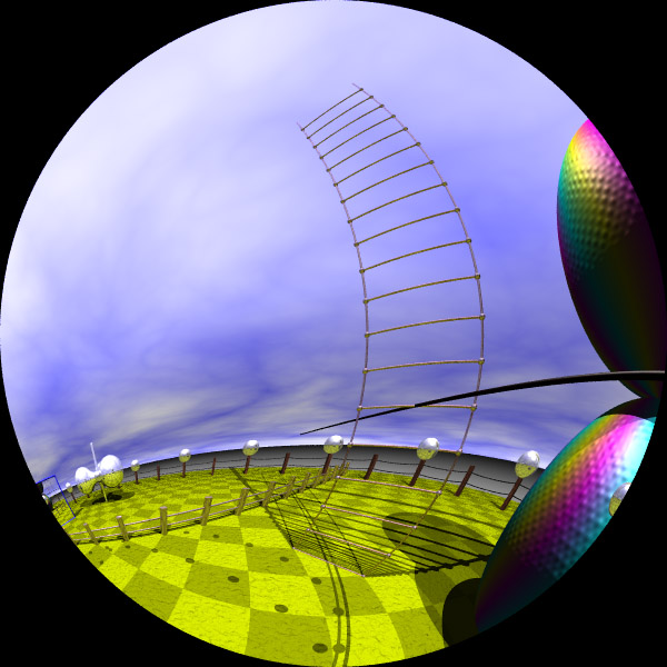
As it happens this is appropriate if the viewer is largely looking forward along a vertical line. The parallax information does disappear towards the sides of the dome. For many applications this may not be a problem, as long as one is using the sides for peripheral vision support and not for depth cues.
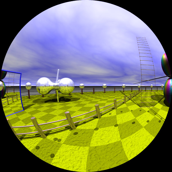
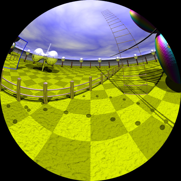
The last approach presented here is called an omni-directional stereoscopic fisheye pair. Omni-directional because it allows the observer to look in any direction (as long as there is a constant "up" vector) and get correct parallax information. This has been implemented as a new camera type called "stereofisheye2".
 |
For example
#declare VP = <0,1,4.5>;
#declare VD = <1,0,0>;
#declare VU = <0,1,0>;
#declare VR = vnormalize(vcross(VD,VU));
#declare EYESEP = 0.07; // Human
#declare ZEROP = 1.5; // Dome radius
camera {
   stereofisheye2
   location VP
   up y
   right -x
   angle 180
   sky VU
   look_at VP + VD
   zeroparallax ZEROP
   eyeoffset 0.5 * clock * EYESEP
      // clock is -1 for left eye, 1 for right eye
}
|

This is very similar in principle to omni-directional stereoscopic panoramic images as well as to the stereoscopic spherical projections discussed earlier. Note that if stereoscopic spherical projections are created then stereoscopic fisheye projections can be derived from for any view direction, this provides the opportunity for interactive panning within a dome environment.
Note that while the tests above have been designed for an upright dome, modifying the projections is straightforward for an inclined or perfectly horizontal dome.