Representing and modelling geometry in SecondLife"SecondLife is not a productivity tool"
Written by Paul Bourke
See also: Evaluating Second Life As A Tool For
Collaborative Scientific Visualisation
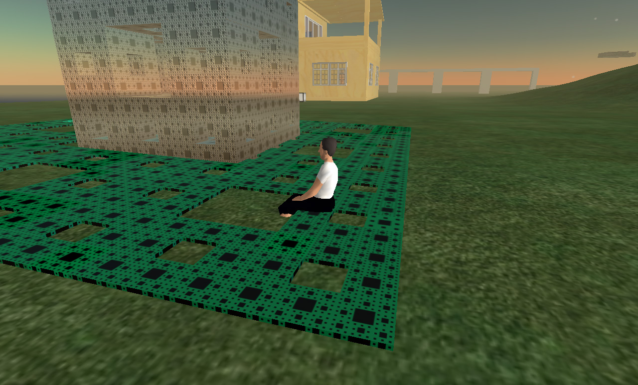
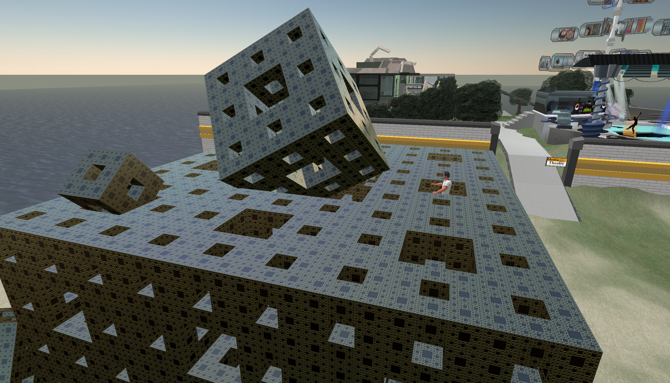
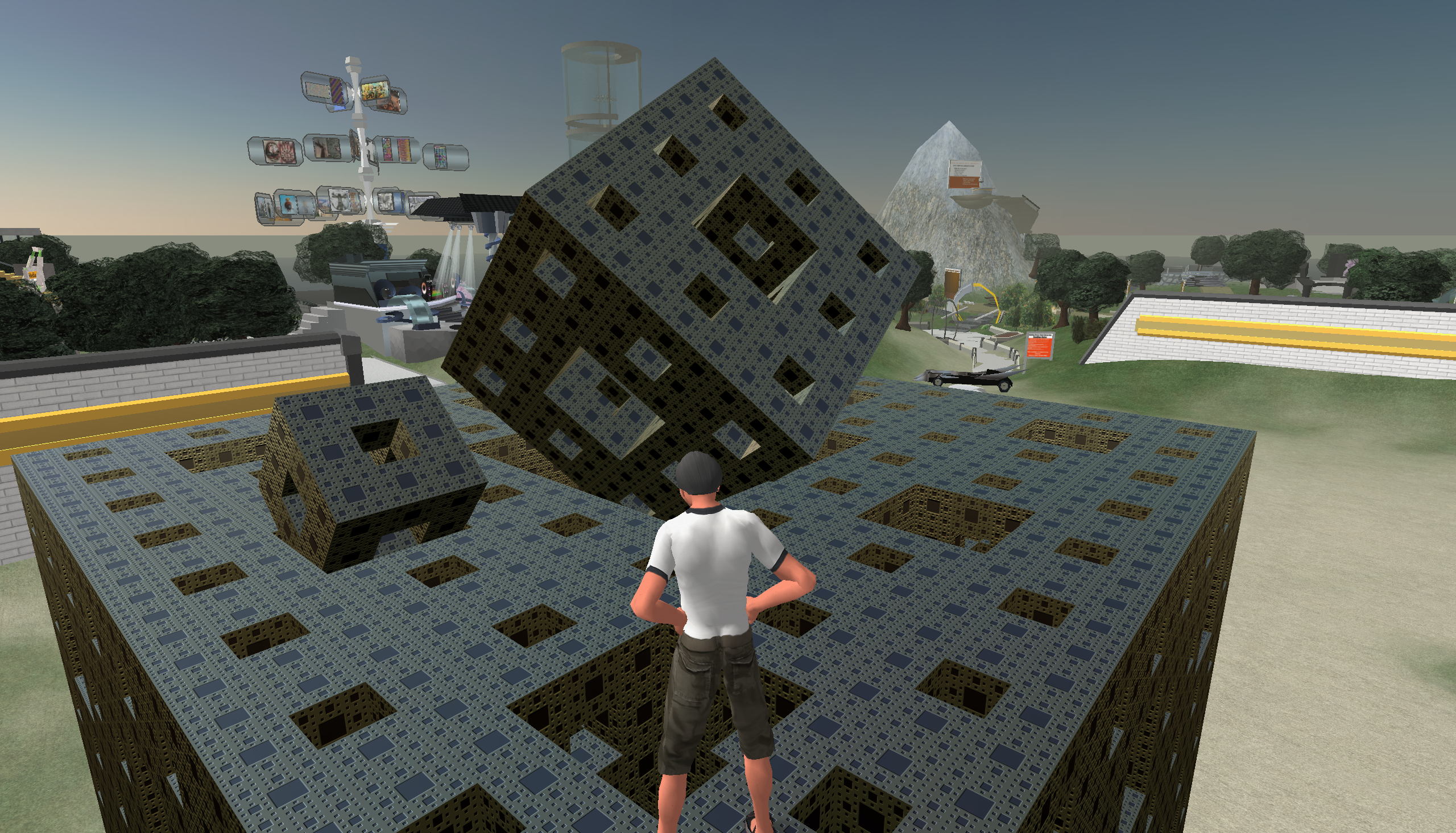
The following are some initial impressions arising from an evaluation of SecondLife (a massively multiplayer online world) as a means of modelling, presenting and interacting with 3D geometry derived mathematically or from datasets. While the original aim was to explore the representation of various fractal forms, the applicability to a range of geometric representations was investigated with the view to using SecondLife as a way of visualising scientific data in a interactive shared (collaborative) environment. The reason why one might consider using something like SecondLife stems from its cross platform support and relatively widespread uptake. The client has a rich 3D interface that allows one to navigate a land based model, interact and communicate with other users, and build objects with programmable behaviours. 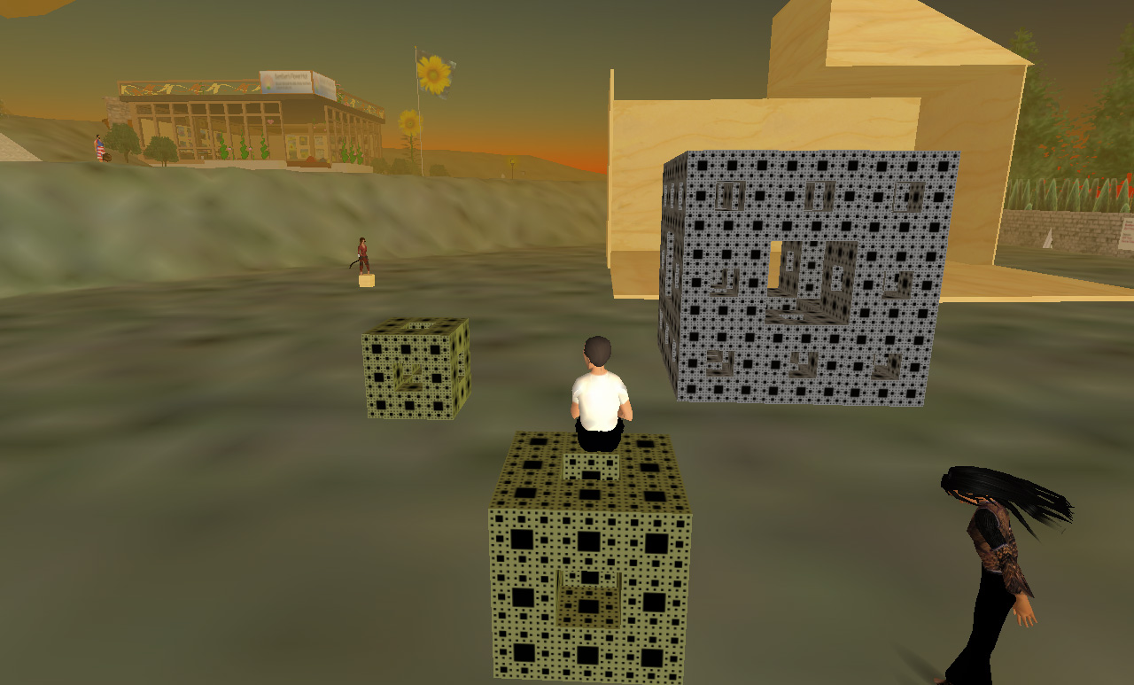 Sitting and surveying ones creation.
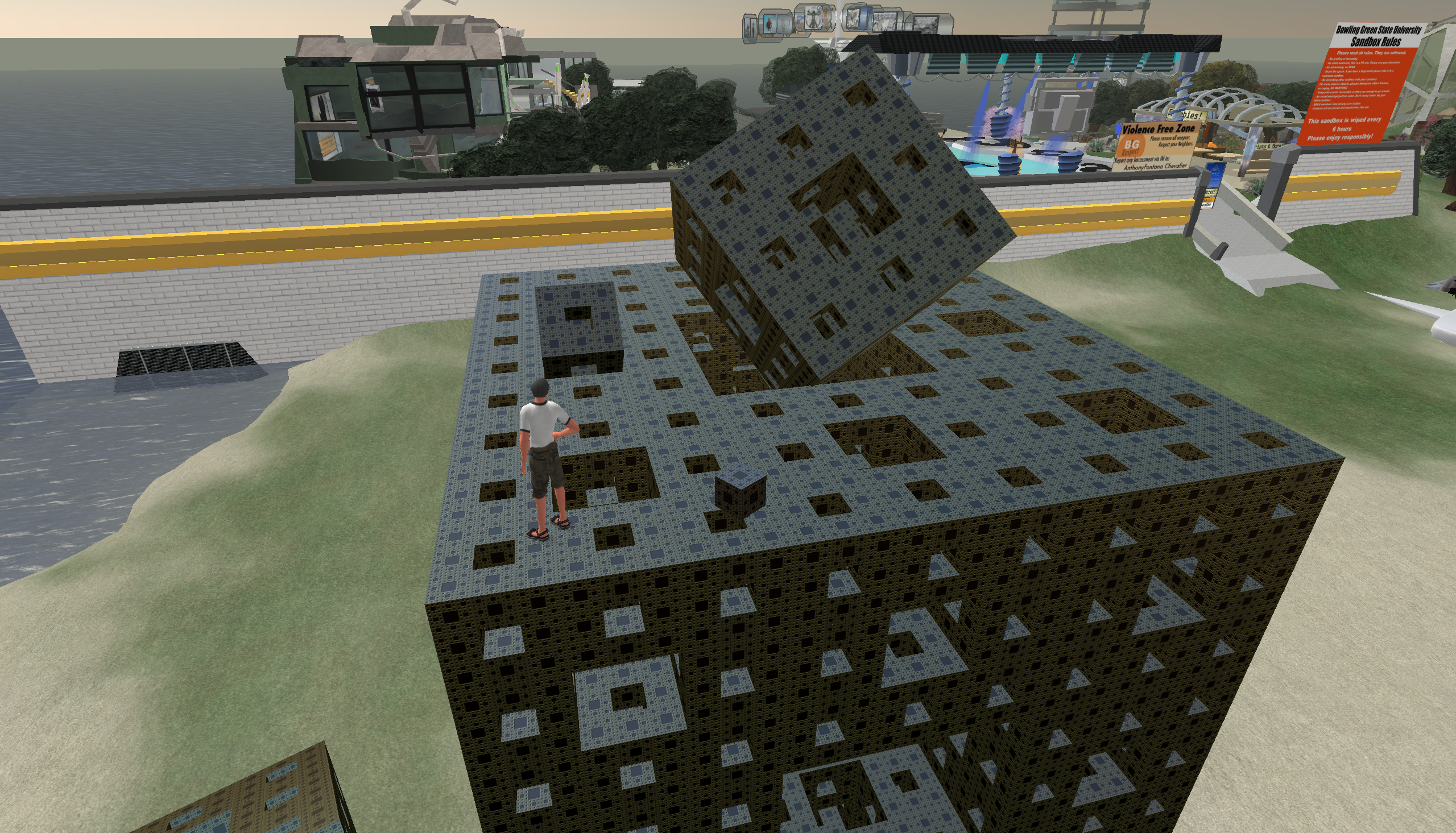
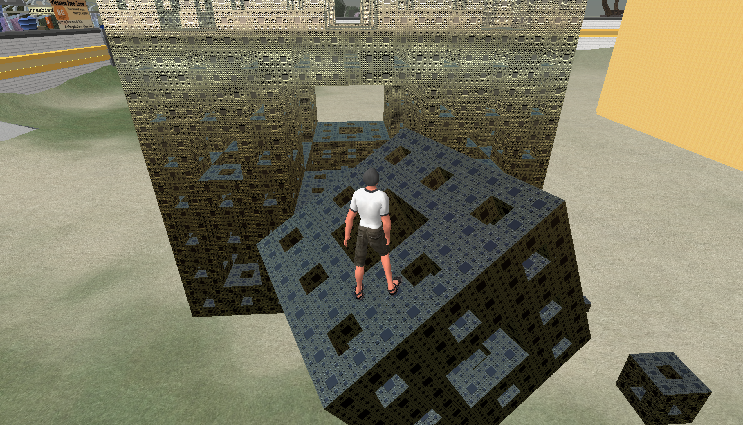
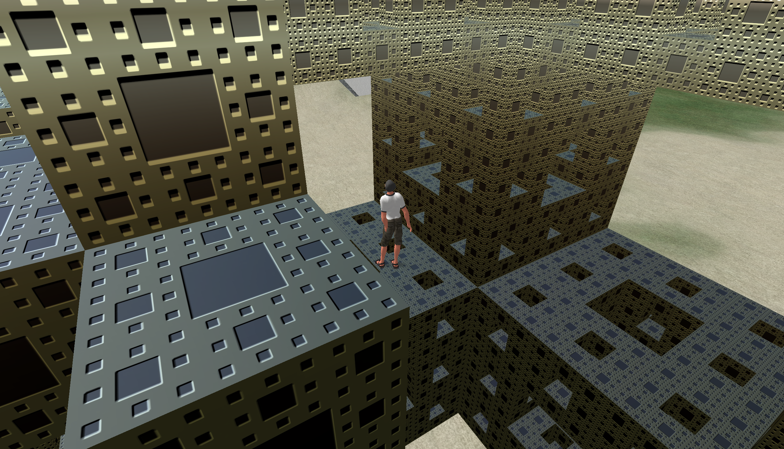
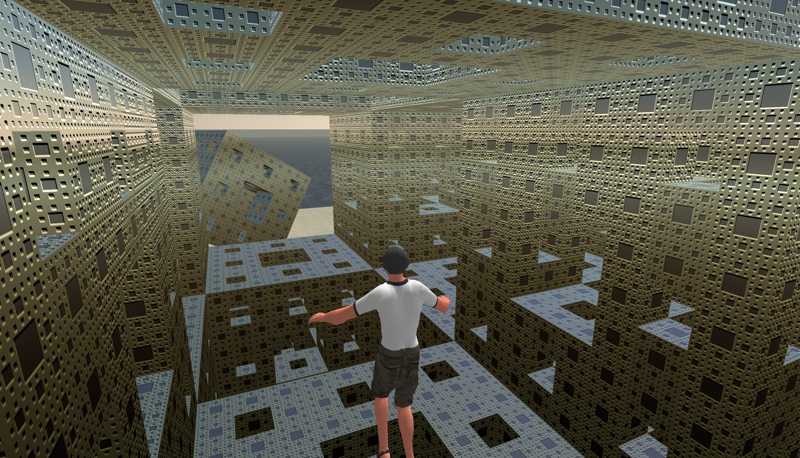
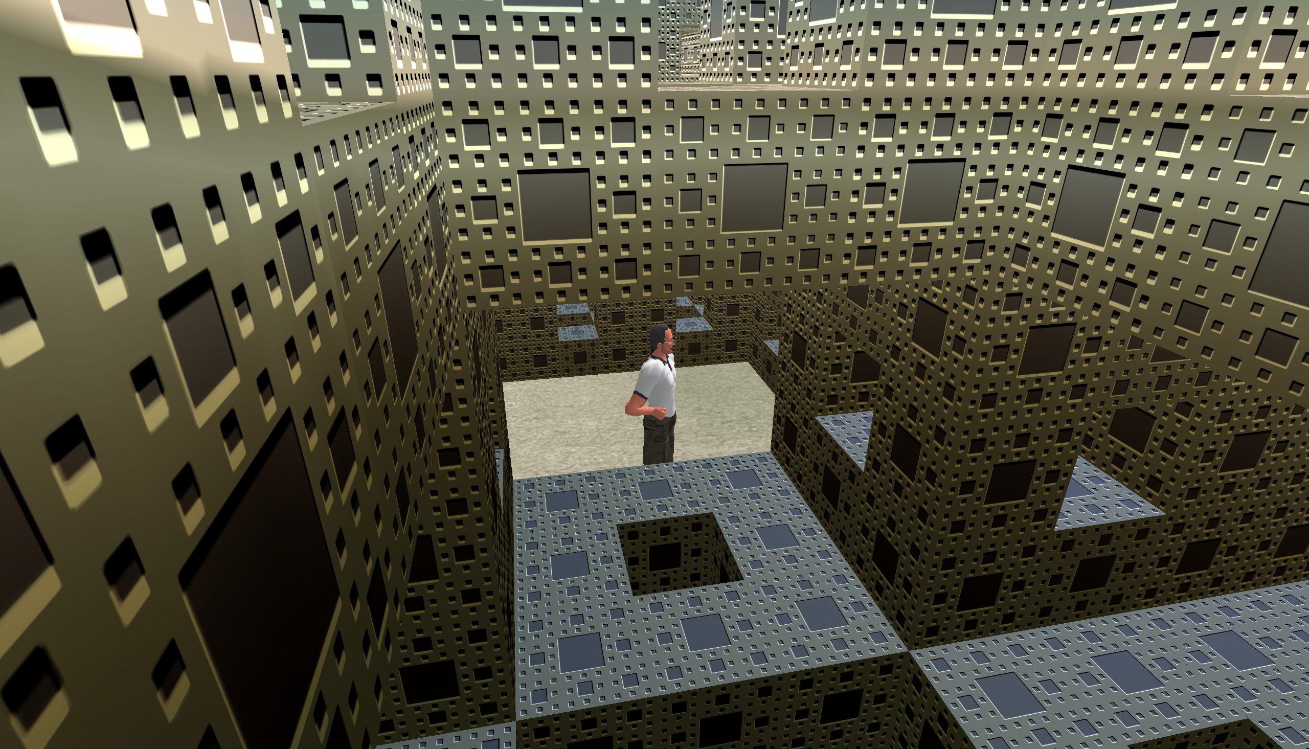
While it can be disabled (phantom objects), by default, all geometry is solid and collision detection is enabled. So in the following Menger sponge one could not get into the center by walking, however there is a flying mode which in this case allows one to enter from the top of the Menger sponge. While most of the screen shots in this document show a third person view, a first person is also supported. 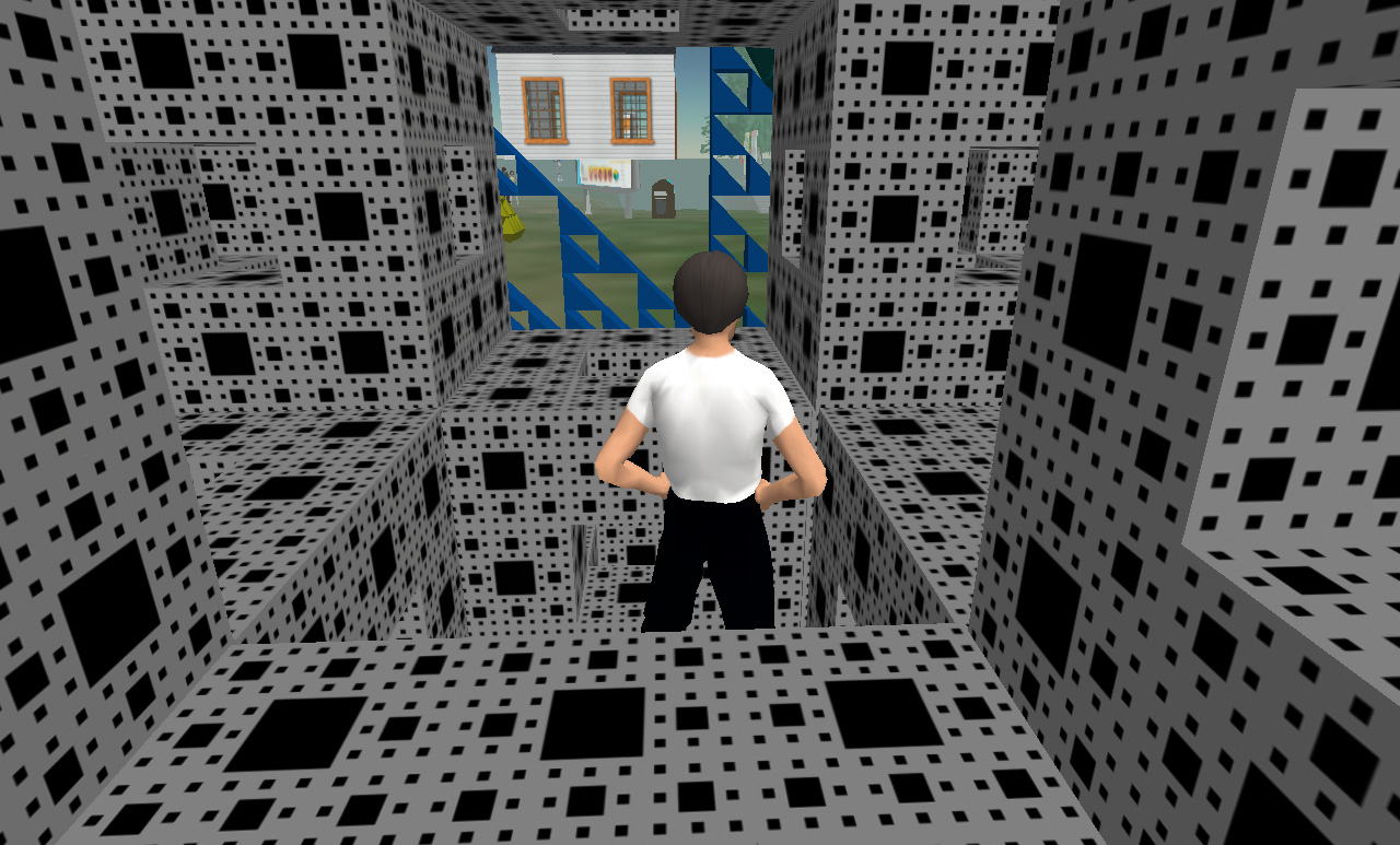 Menger Sponge (400 cube primitives).
The limit on linked objects is a paltry 256 primitives. This limits the ability to group a complicated object as one piece, for easy relocation and adjustment. So, for example, the above sponge at 400 primitives cannot be linked and then moved as one object. While these objects can be created quite quickly by hand, using the built-in primitive editor, they can also be generated by the scripting language within SecondLife called the "Linden Scripting Language". Some examples will be given here but please note I have intentionally only presented very simple examples since this document is not supposed to be a guide to the scripting language. One of the important capabilities of the language as it relates to this evaluation is the ability to "Rez" an object from ones inventory, placing it in the world at a programmed position and orientation. The following makes 20 copies of a level 1 Menger Sponge (called "Buildingblock") thus forming the second level of the Menger Sponge. As you can see the language has a C/C++/Java appearance but with some important differences, mostly simplifications.
default {
    state_entry() {
        llOwnerSay("Touch to start build");
    }

    touch_start(integer total_number) {
        integer i;
        integer j;
        integer k;
        vector p;
        vector offset = <5,0,0>;
        float size = 1.5;

        for (k=-1;k<=1;k++) {
            for (i=-1;i<=1;i++) {
                for (j=-1;j<=1;j++) {
                    if (k == 0) {
                       if (i != 0 && j != 0) {
                            p = llGetPos() + offset + <-size*i,-size*j,k*size>;
                            llRezObject("Buildingblock", p, ZERO_VECTOR, ZERO_ROTATION, 1);
                        }
                    } else if (i != 0 || j != 0) {
                        p = llGetPos() + offset + <-size*i,-size*j,k*size>;
                        llRezObject("Buildingblock", p, ZERO_VECTOR, ZERO_ROTATION, 1);
                    }
                }
            }
        }
    }
}
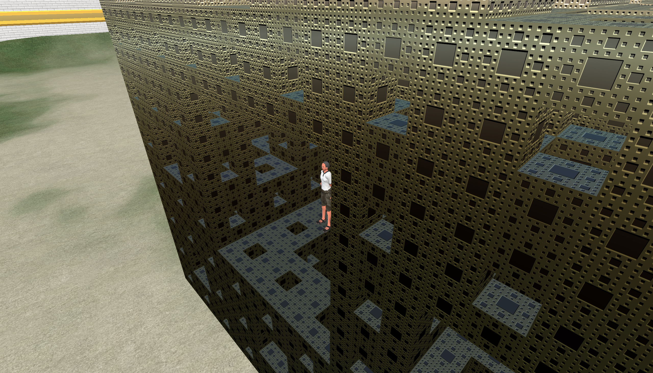
Given an iterative construction process, common in fractal forms, it is quite straightforward to create constructors saving one the mindless need to group/copy/paste/position the elements by hand. The main limitation is the amount of geometry that can be handled, for example, one could not sensibly create the next level of the Menger sponge. Most modelling in SeconeLife, and indeed for many such environments, achieves detail with cunning use of textures. 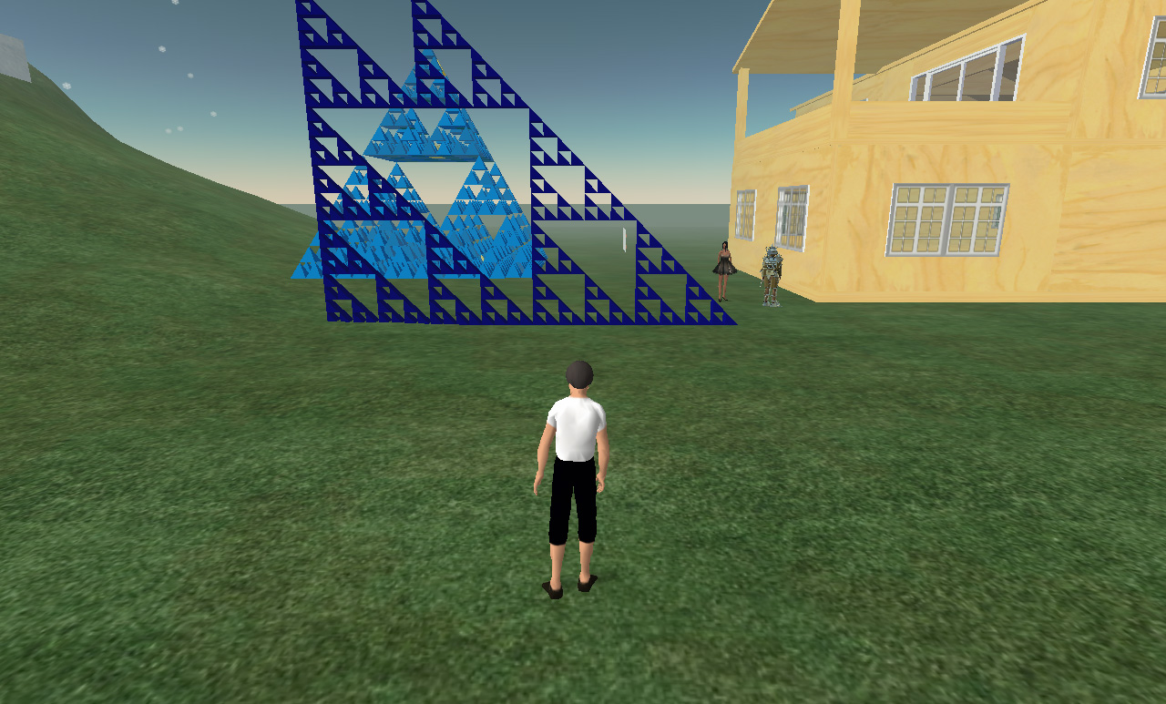
In all the above cases the modelling is performed in what is called a "sandbox", an area where one can model/build but the resulting structures are not permanent although they can be saved in ones own inventory. The way to create a permanent presence is to buy land, unfortunately the number of primitives per square meter is fixed. The bottom line is that for "affordable" land parcels the number of primitives supported isn't terribly exciting for the types of models being explored here. The solution would be to buy a whole island but this is not a low cost venture. Curves, in this case a granny knot, can be produced by Rez'ing primitives along a mathematical path. The usual approach to this is to simply deposit spheres at regular spots along the curve. 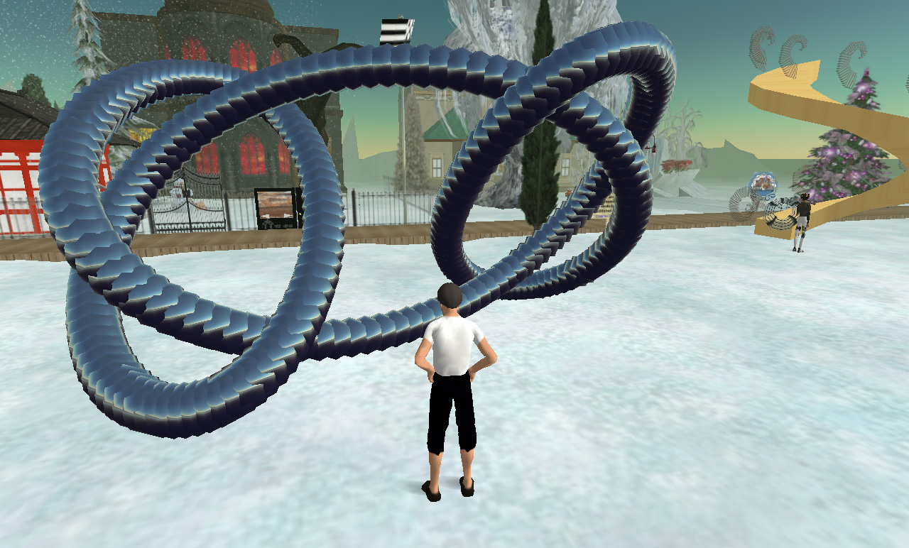 Granny knot.
At the time of writing, creating 256 objects is fairly easy. Creating something made up of 1024 primitives starts to get rather cumbersome. This is not limited (I believe) by current graphics card capabilities but rather by "features" in the SecondLife viewer that manages scene model which are stored remotely. Many of the very impressive looking structures built in SecondLife are to clever use of textures, for this exercise I was more interested in raw geometry representations. An extension to the previous example, one can adjust attributes (colour, size, etc) of a Rez'ed object by creating a handler (called on the on_rez() event) within the instanced objects script.
default {
    state_entry() {
        llOwnerSay("Touch to start build");
    }

    touch_start(integer total_number) {
        integer i;
        vector p;
        vector offset = <5,0,1>;
        float size = 0.2;
        integer n = 256;

        for (i=0;i<n;i++) {
            float t = i * 2 * PI / (float)n;
            vector currentp = llGetPos();
            p.x = 10*(llCos(t) + llCos(3*t)) + llCos(2*t) + llCos(4*t);
            p.y = 6*llSin(t) + 10*llSin(3*t);
            p.z = 4*llSin(3*t)*llSin(5*t / 2) + 4*llSin(4*t) - 2*llSin(6*t);
            llRezObject("c_sphere", currentp + size*p + offset, ZERO_VECTOR, ZERO_ROTATION, i);
        }
    }
}
The following script appears in the instanced object and simply sets the colour of each instance based upon the single argument passed to on_rez(), see the last argument of llRezObject() above. This is essentially an example of how to map colour onto the primitives making up an object, something quite common in many visualisation applications.
default {
    state_entry() {
    }

    on_rez(integer n) {
        float fn = 0.5 * (1 + llCos(10*PI*n / 256.0));
        llSetColor( <0,1-fn,fn>, ALL_SIDES );
    }
}
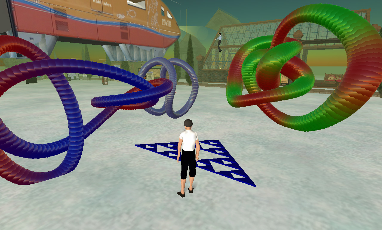 Colour mapped objects
For many types of geometry not defined by equations or repetitive symmetry, one would need to base the geometry on data. The scripting language supports lists (otherwise known in other languages as an array) and these lists can be initialised as they are declared. So one could supply data in a list that is indexed within the script, further this list could be created by some external applications as an export format. The following example shows some polyhedra generated this way, two lists are supplied: one for the vertices and one for the edges, in this case converted from a polyhedra database. The script places spheres at the vertices and represents the edges by correctly aligned/scaled cylinders. The spheres and cylinder instances both have on_rez() handlers to set their dimensions. 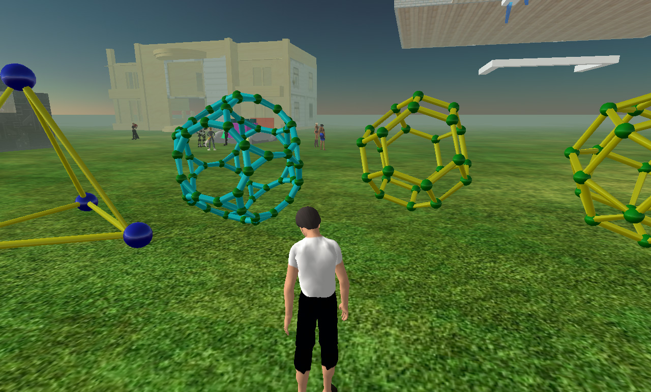 A few examples from the 80 known uniform polyhedra.
list cylinderlist = [
 <0,0,1.0707>, <0.71481,0,0.79718>,
 <0.71481,0,0.79718>, <0.61013,0.70711,0.52363>,
 <0.61013,0.70711,0.52363>, <-0.10468,0.70711,0.79718>,
 <-0.10468,0.70711,0.79718>, <0,0,1.0707>,
      :
      :
     snip
      :
      :
 <0,0,-1.0707>, <0.10468,0.70711,-0.79718>,
 <0,0,-1.0707>, <-0.71481,0,-0.79718>,
 <-0.71481,0,-0.79718>, <-0.61013,-0.70711,-0.52363>,
 <0,0,-1.0707>, <0.10468,-0.70711,-0.79718>
];
list spherelist = [
 <0,0,1.0707>, <0.71481,0,0.79718>,
 <-0.10468,0.70711,0.79718>, <-0.68415,0.20711,0.79718>,
 <-0.10468,-0.70711,0.79718>, <0.61013,0.70711,0.52363>,
 <1.0416,0.20711,0.13677>, <0.61013,-0.70711,0.52363>,
 <-0.35741,1,0.13677>, <-0.78883,-0.5,0.52363>,
 <-0.93688,0.5,0.13677>, <-0.35741,-1,0.13677>,
 <0.35741,1,-0.13677>, <0.93688,-0.5,-0.13677>,
 <0.78883,0.5,-0.52363>, <0.35741,-1,-0.13677>,
 <-0.61013,0.70711,-0.52363>, <-1.0416,-0.20711,-0.13677>,
 <-0.61013,-0.70711,-0.52363>, <0.10468,0.70711,-0.79718>,
 <0.68415,-0.20711,-0.79718>, <0.10468,-0.70711,-0.79718>,
 <-0.71481,0,-0.79718>, <0,0,-1.0707>
];

default {
    state_entry() {
        llOwnerSay("Touch to start build");
    }

    touch_start(integer total_number) {
        integer i;
        vector offset = <0,0,2>;

        vector currentp = llGetPos() + offset;

        // Draw the balls, instance sets the size
        integer ns = llGetListLength(spherelist);
        for (i=0;i<ns;i++) {
            vector p = llList2Vector(spherelist,i);
            llRezObject("ball_blue", currentp + p, ZERO_VECTOR, ZERO_ROTATION, 15);
        }

        // Draw the cylinders, instance sets the size
        integer nc = llGetListLength(cylinderlist);
        for (i=0;i<nc;i+=2) {
            vector p1 = llList2Vector(cylinderlist,i);
            vector p2 = llList2Vector(cylinderlist,i+1);
            rotation rot = llRotBetween(<0,0,1>,p2-p1);
            integer len = (integer)(100*llVecMag(p2-p1));
            llRezObject("pipe_10", currentp + (p2+p1)/2, ZERO_VECTOR, rot, len);
        }
    }
}
The above can obviously be used to represent molecules, the following is the rather simple Aspirin. The colour of the spheres is mapped from the atom type, again using a on_rez() event handler. Unfortunately there is a rather small limit to the list size supported by the script compiler, a molecule consisting of about 300 atoms and 300 bonds could not be compiled (memory error). Another annoying limitation is the linking/grouping of objects together is flat rather than hierarchical, this limits the scope for managing more complicated structures from smaller building blocks. 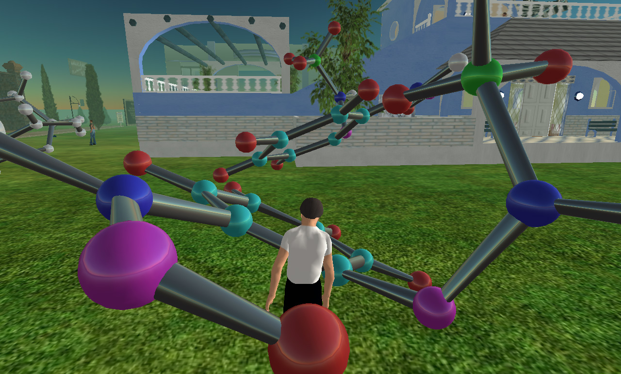 Aspirin molecule
One solution for larger structures based upon data in lists, while messy, is to build the structure up out of multiple sections. The following is created in two passes, that is, two lists each containing half of the molecule. As before this structure is exported from a molecular database. This was a good example of the collaborative potential of such environments. The vast majority of people in SecondLife seem to be building houses, vehicles, and accessories. These are for the most part created using the built-in editing/modelling tools. So when they see something "different" it tends to generate interest and often an ensuing discussion. 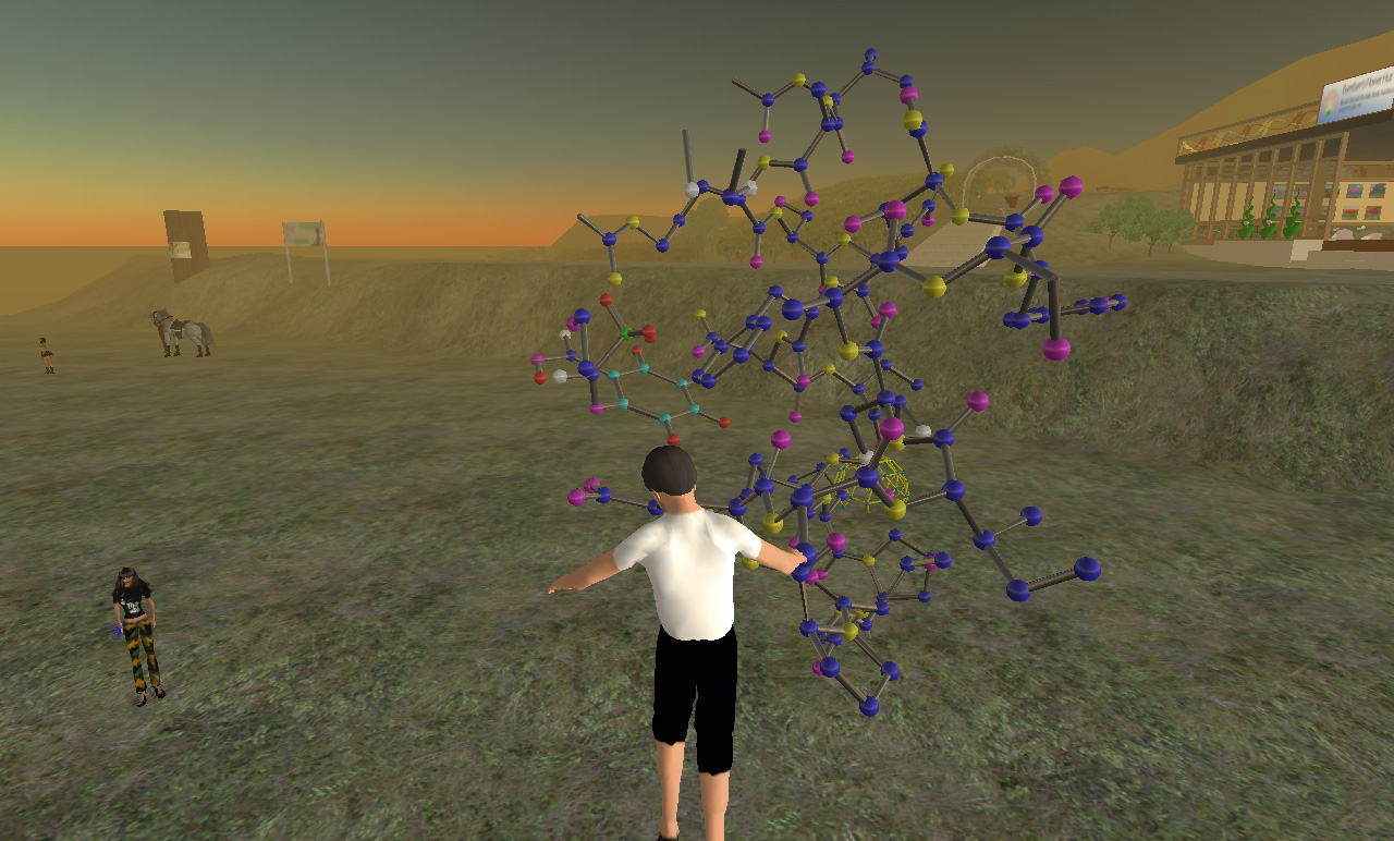 Crambin protein. 327 atoms, 334 bonds.
While arbitrary surface meshes aren't supported, one can make meshes of parametric surfaces using the same aligned and scaled cylinders as described above. One might imagine using this to create animated chaotic attractors, but generating dynamic geometry seems to be far too slow, again most of the animation one sees in SecondLife is achieved with animated textures or static geometry with associated behaviours. 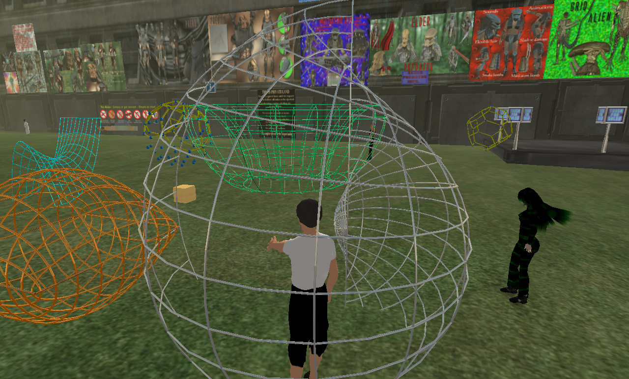 Parametric surfaces.
While not a serious problem, individual primitives are limited to 10m in any dimension. In cases where one might want to map cylindrical, or in this case, spherical projections onto geometry which is then experienced from the interior, larger structures would be more convenient. 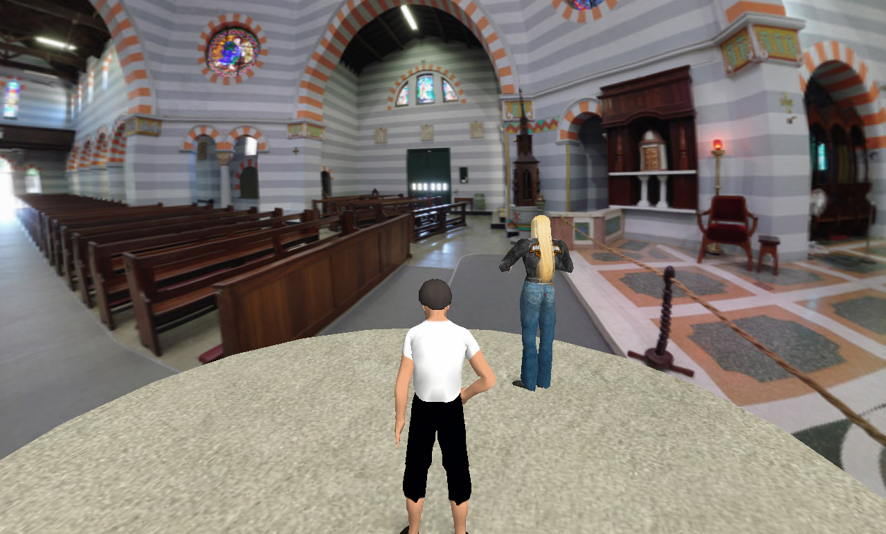 Spherical projection: Cathedral at Geraldton, West Australia
There is a limit of 1024 pixels for textures, if one uploads a larger texture it will be scaled so that no dimension is greater than 1024. This is rather low resolution for panoramic presentation, the solution is simply to split the panoramic image up into bits and apply each to a separate piece of geometry. In the following the panorama is split into 4 sections, each 1024 wide and each applied to 1/4 of a cylinder for a resulting resolution of 4096. 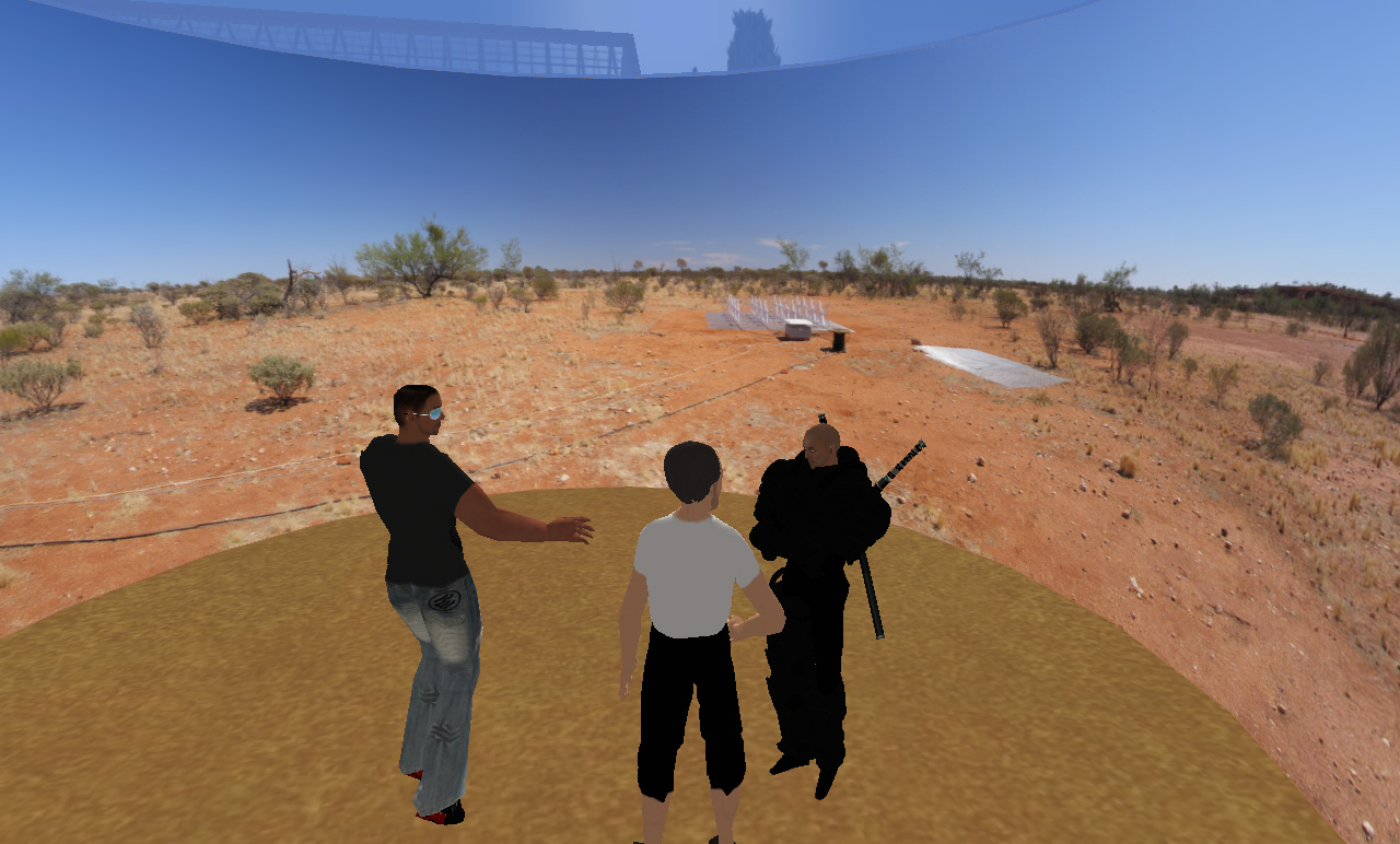 Cylindrical projection: Wide Field array tile, Boolardy, West Australia
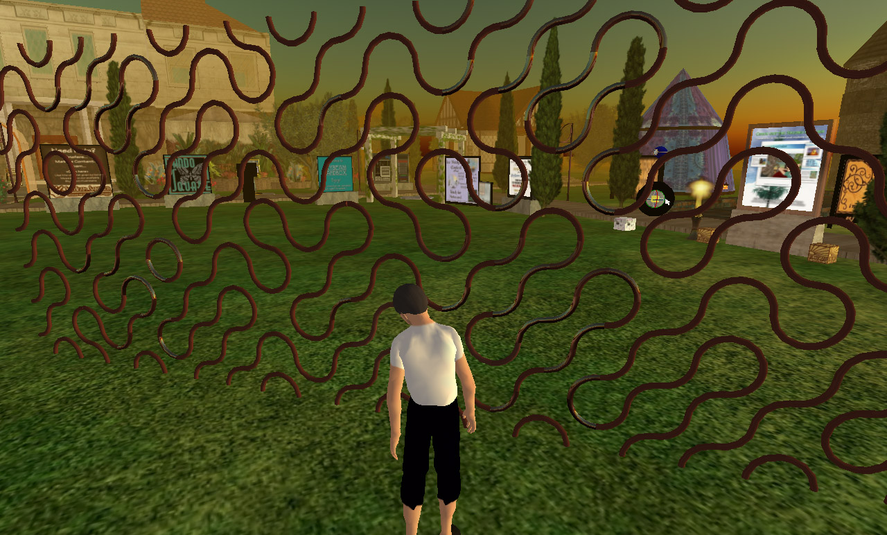 2D Truchet tiles
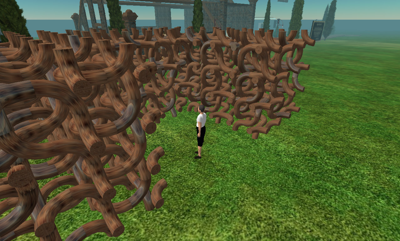 3D Truchet tiles
SecondLife does support sculpt textures, that is, images that are applied as spherical maps but whose r,g,b values are interpreted as x,y,z radial offsets to the x,y,z vertices. In the following these have been used to create spherical harmonics, which also have a standard circular colour ramp applied. The sculpt maps themselves are also given below. While it is normally expected that one would create these in a modelling package that supports sculpt maps, these have been created in code from a knowledge of the surface mathematics. 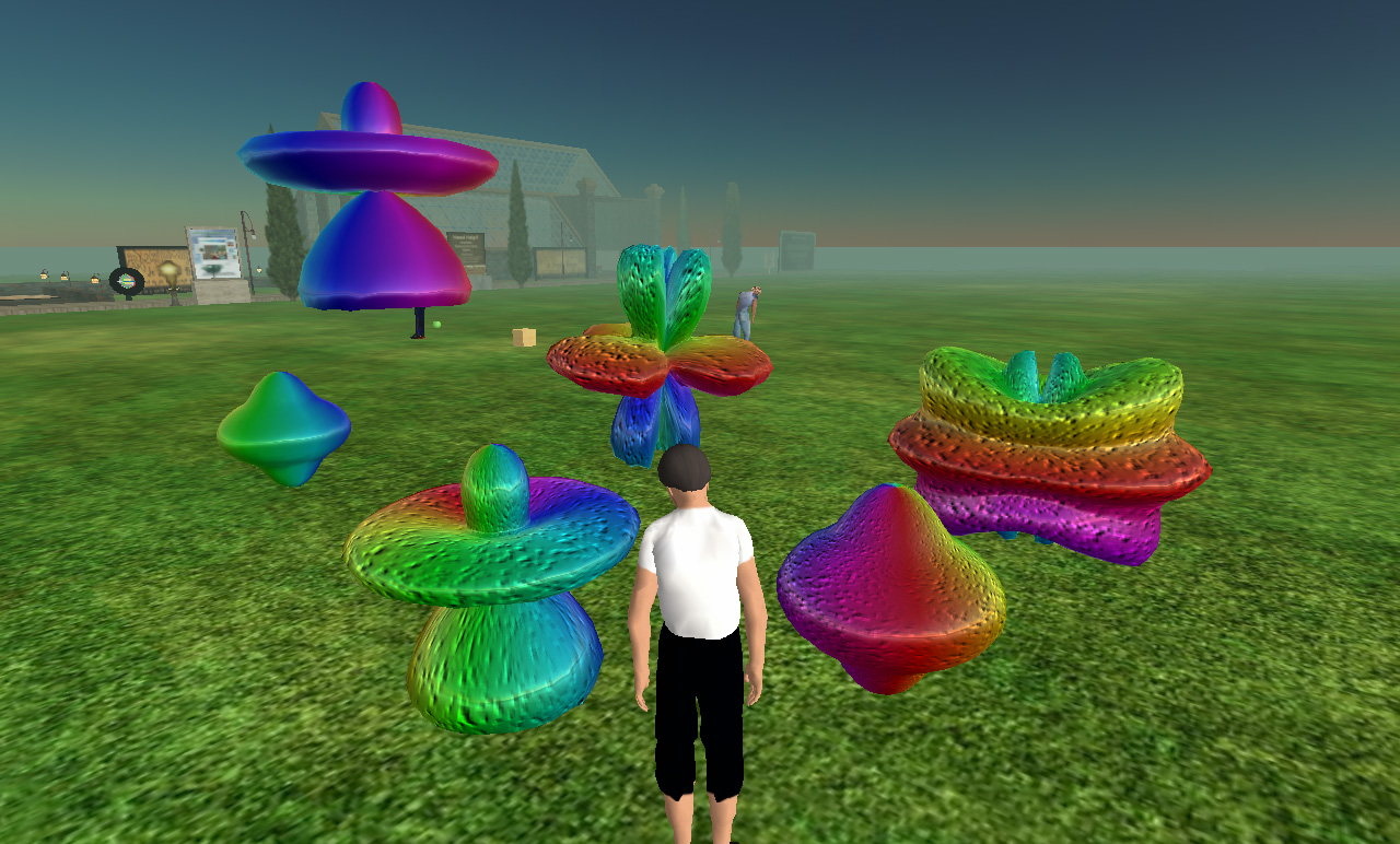 Spherical harmonics
A sample of some plain/simple C code that creates a sculpt image for the spherical harmonics is given below. The colours r,g,b are directly mapped to x,y,z. A byte value of 128 is zero.
int main(int argc,char **argv)
{
   int N = 128;                     // Size of the sculpt image, square
   int i,j,pass,index;
   double theta,phi,r;
   XYZ p;
   PIXEL c,*image = NULL;
   double m[8] = {5,0,5,1,3,3,3,2}; // An example set of parameters
   double themax = 0;               // Used to scale the object to +-128

   // Initialise the image here and erase to 50% grey (zero) ....

   // Sample over polar coordinates
   // On the first pass find the range, draw image on second pass
   for (pass=0;pass<2;pass++) {
      for (j=0;j<N;j++) {
         for (i=0;i<N;i++) {
            theta = i * TWOPI / (double)N;      // 0 to 2pi
            phi = -PID2 + PI * j / (double)N;   // -pi/2 to pi/2
            r = pow(sin(m[0]*phi),m[1]) + pow(cos(m[2]*phi),m[3]) +
                pow(sin(m[4]*theta),m[5]) + pow(cos(m[6]*theta),m[7]);
            p.x = r * cos(phi) * cos(theta);
            p.y = r * cos(phi) * sin(theta);
            p.z = r * sin(phi);
            if (pass == 1) {
               c.r = 128 + p.x * 127 / themax;
               c.g = 128 + p.y * 127 / themax;
               c.b = 128 + p.z * 127 / themax;
               image[i][j] = c;
            } else {
               themax = MAX(themax,fabs(p.x));
               themax = MAX(themax,fabs(p.y));
               themax = MAX(themax,fabs(p.z));
            }
         }
      }
   }

   // Save the image here ...
}
Each object here is a sphere transformed by the sculpt map, in reality it can be almost any of the geometric primitives supplied in the SecondLife editor. Note that colours, texture and bump maps can still be applied ... the sculpt map is entirely independent of the materials. One of the elegant aspects of these sculpt maps is that that multiple levels of detail can be implemented simply by subsamping the sculpt map images. 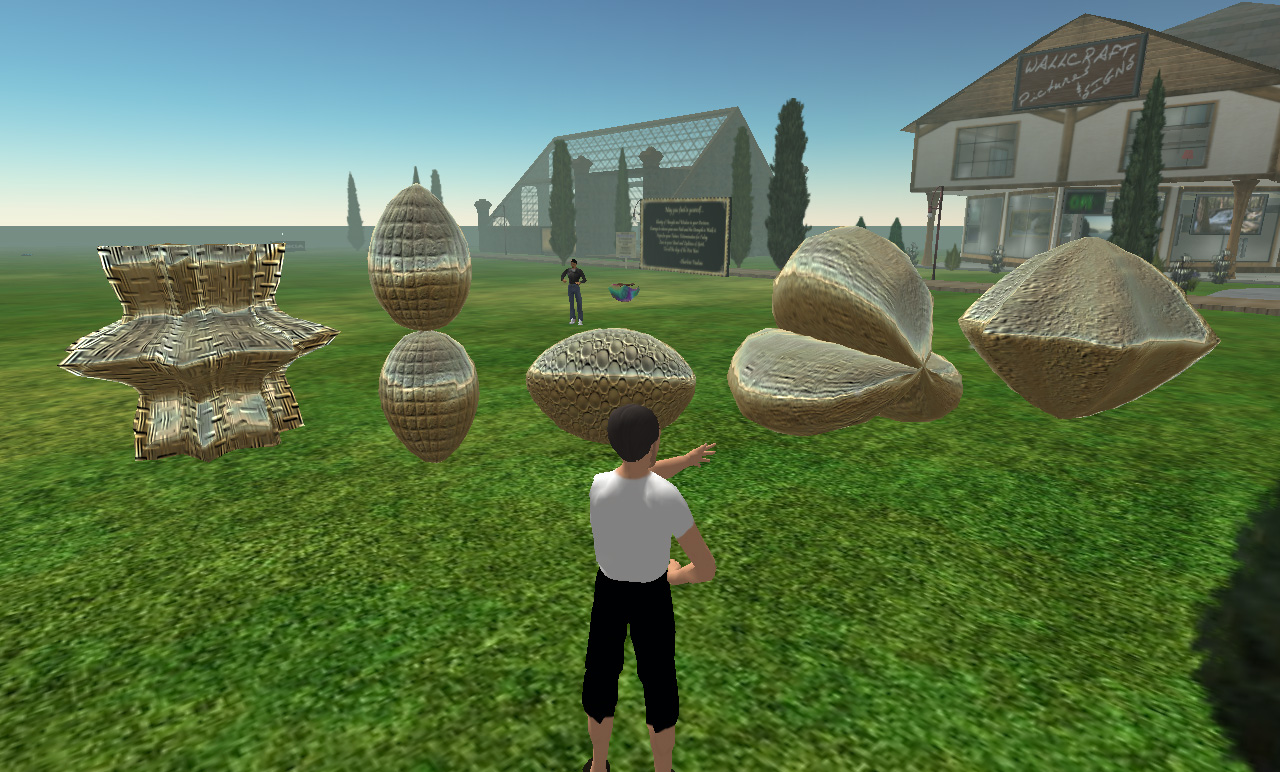 3D Supershapes
Volume rendering example: As one might imagine, a series of boxes, one per slice and each having the appropriate texture plane. Mostly demonstrates that transparency is handled correctly even with a large number of planes. 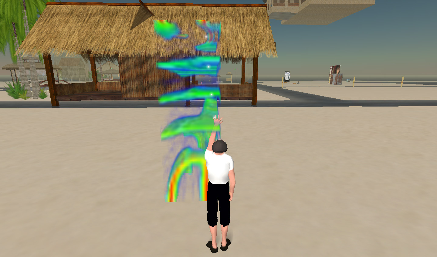 Helical waves paper
Molecular visualisation example by creating a spherical map. While the appearance of real geometry is very powerful, this is just an image wrapped onto a sphere. 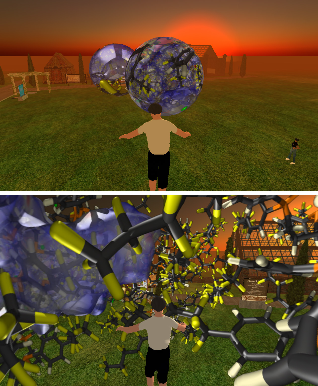
There are a number of limitations mentioned above that impact upon the usefulness of SecondLife for what I originally had in mind, namely a platform in which to present and convey geometry, fractals, and visualisation. I should note that these should not necessarily be seen as criticisms, in most cases I fully appreciate the reasons for the limitations. Indeed even with the limitations as they stand there is plenty of abuse that occurs in the public spaces in SecondLife that impact upon the experience of the "average" participant.
Menger Sponge in Second LifeProduced by Paul BourkeFebruary 2008
|